ALIEN TECHNOLOGY® ALR-F800 HARDWARE SETUP GUIDE November 2019 ALR-F800
Legal Notices Copyright ©2017 Alien Technology, LLC. All rights reserved. Alien Technology, LLC has intellectual property rights relating to technology embodied in the products described in this document, including without limitation certain patents or patent pending applications in the U.S. or other countries. This document and the products to which it pertains are distributed under licenses restricting their use, copying, distribution and de-compilation.
Ce dispositif a été conçu pour fonctionner avec une antenne ayant un gain maximum de 6 dBiL. L’impédance d'antenne requise est de 50 ohms. Pour réduire les interférences radio potentielles pour les autres utilisateurs, le type d'antenne et son gain doivent être choisis afin que la puissance isotrope équivalente (PIRE ) ne soit pas supérieure à celle requise pour une bonne communication.
TABLE OF CONTENTS Alien Technology® Hardware Setup Guide ALR-F800 June 2017 Table of Contents CHAPTER 1 INTRODUCTION ..................................................................................................................... 1 RFID Reader Overview ................................................................................................................................. 1 EPC Class 1 GEN 2 UHF RFID Tags .......................................................................................
CHAPTER 1 INTRODUCTION CHAPTER 1 Introduction This Hardware Setup Guide provides instructions for installing and operating the ALR-F800 RFID Readers. This document is designed for use by RFID system integrators and software developers - those who wish to develop software products and extended systems that take full advantage of the RFID Reader's capabilities.
CHAPTER 1 INTRODUCTION Additionally, the RFID Reader Developer's Kit includes the following items: One (1) ALR-8696-C antenna One (1) RS-232 serial cable (to connect to host computer) One (1) Network cross-over cable Download instructions for demonstration software, user guides, documentation and the Alien RFID Gateway Application Software APIs and example code An assortment of Class 1 Gen 2 UHF tags EPC Class 1 GEN 2 UHF RFID Tags The Alien ALR-F800 RFID reader is designed to read
CHAPTER 1 INTRODUCTION Specifications Specifications for key components of the RFID Reader system are provided in the tables below. Only these listed components may be used in the RFID reader system. The reader table refers to US or ETSI specifications only. Reader models released for the other countries may have different power levels, frequency of operation and channel spacing in compliance with local regulations where the product is sold.
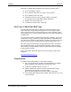
CHAPTER 1 INTRODUCTION Mechanical: Reader Physical Size Figure 1 - Outline Drawing of the ALR-F800 (mm) RFID Reader High Performance Circular Antenna Model ALR-8696-C 3 dB Beamwidth E-plane: 65 degrees H-plane: 65 degrees Frequency 865-960 MHz Gain (dBi) 6.0 dBiL (maximum) Polarization Circular RF Connector 6 m LMR-195 with Reverse-Polarity TNC VSWR 1.5:1 Dimensions (cm) 26 x 26 x 3.4 (in) 10.2 x 10.2 x 1.32 Weight 1.1 kg 2.5 lb ALR-F800 HARDWARE SETUP GUIDE DOC.
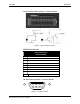
CHAPTER 1 INTRODUCTION I/O Port Terminal Interface The ALR-F800 I/O port provides four digital inputs and eight digital outputs, optically isolated from the reader circuitry for use in noisy industrial environments. Opto-isolators have two basic elements: a light source (usually a light emitting diode) and a photo-sensitive detector. These two elements are positioned facing one another and inserted in an electrical circuit to form an optocoupler.
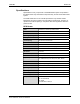
CHAPTER 1 INTRODUCTION I/O PORT SCREW TERMINAL (FEMALE) – LOOKING AT READER Figure 2 - Input and Output Circuits RS-232 Port Pin-outs RS-232 Connector (Female DB-9F) Pin 1 DCD Connected to Pin 6 Pin 2 TR1 Transmit Data (Output) Pin 3 RC1 Receive Data (Input) Pin 4 DTR Connected to Pin 6 Pin 5 Ground Pin 6 DSR Connected to Pin 4 Pin 7 RTS Connected to Pin 8 Pin 8 CTS Connected to Pin 7 Pin 9 Not Connected RS-232 CONNECTOR (FEMALE) – LOOKING AT READER 5 4 9 3 8 2 7 1 6 Figure 3 - RS
CHAPTER 1 INTRODUCTION USB Ports There two USB ports on the back of the ALR-F800 reader USB-A and USB-B. They are both female connectors and their functionality is as follows: USB-A is used to connect various USB devices including USB flash drives, Wi-Fi and Bluetooth adapters. USB-B is used as a serial console for either Alien Reader Protocol interface or Linux OS login.
CHAPTER 1 INTRODUCTION System Architecture Figure 4 - System Architecture for the ALR-F800 Reader ALR-F800 HARDWARE SETUP GUIDE DOC.
CHAPTER 2 READER HARDWARE INSTALLATION AND OPERATION CHAPTER 2 Reader Hardware Installation and Operation This chapter describes the RFID Reader and provides installation and operation information. Receiving the RFID Reader Your RFID Reader is shipped with the items listed below. Please verify the contents of your received shipment before assembling. RFID reader The RFID Reader Kit is shipped with the items listed below.
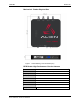
CHAPTER 2 READER HARDWARE INSTALLATION AND OPERATION Figure 5 - ALR-F800 Reader (Antennas and tag kit not shown) Reader Antenna Panel 4 Antenna Ports (RP-TNC) ALR-F800 HARDWARE SETUP GUIDE DOC.
CHAPTER 2 READER HARDWARE INSTALLATION AND OPERATION Reader I/O Panel The I/O panel (shown below) includes the following( Left to Right): LAN TCP/IP and PoE port Auxiliary DC Power connector Reset button USB A USB B SDCard 9-pin D female RS-232 serial port 16-pin I/O terminal block (GPIO) Figure 6 - ALR-F800 Reader Connections Diagnostic LEDs The ALR-F800 includes diagnostic LEDs on the face of the reader to provide easy and convenient external indication for various opera
CHAPTER 2 READER HARDWARE INSTALLATION AND OPERATION Figure 7 – ALR-F800 Front Panel Reader Diagnostic LEDs Reader Antennas The ALR-F800 includes 4 antenna ports. These antenna ports are a reversepolarity TNC connector. Only antennas documented in this manual (FCC approved) may be used with the ALR-F800. System Assembly and Bench Test Assembling the RFID Reader system is easy.
CHAPTER 2 READER HARDWARE INSTALLATION AND OPERATION 2. Connect the RS-232 cable or USB B to the reader. Align the male cable connector so that its shape and pins match the shape and holes of the female DB-9 RS-232 port. Figure 9 - RS-232 Connector Push the aligned connector into the port. Finger-tighten the screws to secure the cable/connector to the reader. 3. Connect the RS-232 cable to the serial port on the PC.
CHAPTER 2 READER HARDWARE INSTALLATION AND OPERATION If you are using the AC/DC power brick, connect a cross-over Ethernet cable to the ALR-F800 LAN/PoE port and to the PC LAN port. Figure 10 – PoE Power Supply and Network Connection Diagram Figure 11 – 12V DC cord and Network Connection Diagram The reader comes preconfigured to look for a DHCP server to set its network parameters. In the absence of a DHCP server, the reader will use the following settings: ALR-F800 HARDWARE SETUP GUIDE DOC.
CHAPTER 2 READER HARDWARE INSTALLATION AND OPERATION IP Address: 192.168.1.100 Subnet Mask: 255.255.255.0 Gateway: 192.168.1.1 6. Connect the antenna to the antenna port. The ALR-F800 is a mono-static system (a single antenna acts as both transmitter and receiver). Four antenna ports (ANT 0-3) are provided. Each antenna provides a single read point. Only the antennas listed in this manual and their associated cables (if specified) may be used with this reader.
CHAPTER 2 READER HARDWARE INSTALLATION AND OPERATION --------------------------------Network Settings: MAC Address : 00:1b:5f:00:e8:bb Hostname : alr-00e8bb IP Address : 10.10.81.101 Netmask : 255.255.255.0 Gateway : 10.10.81.1 DHCP : on DHCP Timeout: 60 IPv6 Address: fdaa::aaaa IPv6 Netmask: 112 IPv6 Gateway: fdaa::1 IPv6 DHCP : on DNS : 10.1.4.22 10.1.4.23 TimeServer : 128.138.140.
CHAPTER 2 READER HARDWARE INSTALLATION AND OPERATION Installation This section provides guidance for configuring components in your RFID system. You should consider the overall design of your specific system before permanently mounting the equipment. Installation involves many of the same connection steps required for bench test. However, instead of placing equipment on a tabletop, the reader, antenna, and their accessories are mounted in your application environment.
CHAPTER 2 READER HARDWARE INSTALLATION AND OPERATION reader base and the mounting plate. When mounting vertically the reader IO panel should be oriented at the bottom. Antennas should be placed close enough to the reader to accommodate the cable length without putting strain on the connectors. Mount units individually. Do not stack them. 3. Install the reader.
CHAPTER 2 READER HARDWARE INSTALLATION AND OPERATION If you are using the PoE power supply, use a short standard Ethernet cable to connect the reader’s RJ-45 jack to the LAN+DC RJ-45 jack of the power supply. Align the RJ-45 connector with the corresponding TCP/IP port on the reader or the power supply and push the connector in. If you are using the optional DC power cord, connect the DC power jack into the DC power plug of the reader. Tighten the screw fitting finger tight.
CHAPTER 2 READER HARDWARE INSTALLATION AND OPERATION Gateway application which is a demonstration program also included in your download instructions. For more details, refer to either the Reader Interface Guide or the Demonstration Software Guide described briefly below. Reader Interface Guide The Alien Reader Protocol, mentioned previously, is described in detail in the Reader Interface Guide.
CHAPTER 2 READER HARDWARE INSTALLATION AND OPERATION • RFID System Architecture and Integration • Conducting Site-surveys & Contending with Interference Please visit http://www.alientechnology.com for more information. ALR-F800 HARDWARE SETUP GUIDE DOC.
CHAPTER 2 READER HARDWARE INSTALLATION AND OPERATION Approved High Performance Circular Antennas Approved w/Multiplexer Model Frequency Gain (dBi) Polarization RF Connector VSWR Dimensions Weight ALR-8696-C 865-960 MHz 6.0 dBiL (max) Circular 6 m LMR-195 with RP- TNC* 1.5:1 (cm) 26.0 x 26.0 x 3.4 (in) 10.20 x 10.20 x 1.32 1.10 kg 2.5 lb ALR-8698 865-928 MHz 8.5 dBiL (max) Circular RP- TNC 1.3:1 (cm) 25.8 x 25.8 x 3.6 (in) 10.16 x 10.16 x 1.42 0.9 1kg 2.
CHAPTER 2 READER HARDWARE INSTALLATION AND OPERATION Appendix A ALR-F800-EMA Operating Frequency and Power Minimum Frequency 865.7 MHz ALR-F800 HARDWARE SETUP GUIDE DOC. CONTROL #8102141-000 REV E Maximum Frequency 867.5 MHz EIRP 35.
CHAPTER 2 READER HARDWARE INSTALLATION AND OPERATION Appendix B: Declaration of Conformity This declaration of conformity is issued under the sole responsibility of Alien Technology, LLC. Radio Equipment: Model: ALR-F800-EMA Brand: ALR-F800 ALR-F800-X Manufacturer Alien Technology, LLC 845 Embedded Way San Jose, CA 95138 1.408.782.3900 www.alientechnology.com EU Authorized Representative Alien Technology LLC Stephen Crocker Director, Sales/Channels EMEA and India scrocker@alientechnology.com www.