
Manual

9
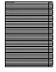
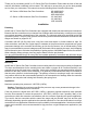
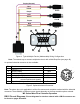
Figure 4. Typical Multiple Device (Addressable) Wiring Conguration
Note: The easiest way to connect multiple devices is with a Multi-Drop Box (see page 46).
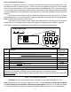
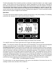
An optional industrial connector is also available:
1
6
5
4
3
2
Pin Function Cable Color
1
Power In (
+ )
Red
2 RS-232 Output Blue
3 RS-232 Input Signal White
4 Analog Input Signal Green
5 Ground (common for power,
communications and signals)
Black
6 Signal Out (Voltage or Current as ordered) Brown
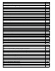
Figure 5. Optional Industrial Connector
Note: The above pin-out is applicable to all the ow meters and controllers ordered with the industrial
connector. The availability of different output signals depends on the ow controller options ordered.
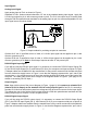
MC Series Mass Flow Controller Operation
DB15 Pin-out Diagrams: Pin-out diagrams for devices ordered with a DB15 connector can
be found on pages 49 and 50 .
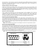
5
3
2
Purple
Red
Yellow
Purple
Red
Yellow
5
4
3
2
1
9
8
7
6
Unit C
Unit B
Unit A
Female Serial Cable Front
Purple (Ground)
Red
Yellow