
Manual


6
Power and Signal Connections
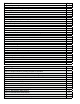
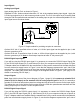
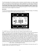
Power can be supplied to your MC or VC Series controller through either the power jack or the 8 pin
Mini-DIN connector as shown in Figure 1. Power may also be supplied through an AC to DC adapter
which converts line AC power to DC voltage and current as specied below. The power jack accepts
2.1 mm female power plugs with positive centers. Cables and AC/DC adaptors may be purchased
from the manufacturer (see Accessories page 48) and are commonly available at local electronics
suppliers.
Small Valve: If your controller utilizes a small valve (about the size of your thumb), a 12-30Vdc
power supply with a 2.1 mm female positive center plug capable of supplying 250 mA is recommended.
Note: 4-20mA output requires at least 15 Vdc.
Large Valve: If your controller utilizes a large valve (about the size of your st), a 24-30 Vdc power
supply with a 2.1 mm female positive center plug capable of supplying at least 750mA is required.
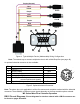
Alternatively, power can be supplied through the Mini-DIN connector as shown below:
7
8
1
2
3
4
5
AC/DC Adapter Jack
6
1
3
2
4 5
6
7
8
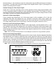
Pin Function
Mini-DIN
cable color
1
Inactive or 4-20mA Primary Output Signal Black
2
Static 5.12 Vdc or Secondary Analog Output (4-20mA, 5Vdc, 10Vdc)
or Basic Alarm
Brown
3 RS-232 Input Signal Red
4 Analog Input Signal Orange
5 RS-232 Output Signal Yellow
6
0-5 Vdc (or 0-10 Vdc) Output Signal Green
7 Power In (as described above) Blue
8 Ground (common for power, communications and signals) Purple
Note: The above pin-out is applicable to all the ow meters and controllers available with the Mini-DIN
connector. The availability of different output signals depends on the options ordered.
Underlined Items in the above table are optional congurations that are noted on the unit’s calibration
sheet.
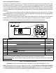
Figure 1. 8 Pin Mini-DIN Connector
CAUTION: Do not connect power to pins 1 through 6 as permanent damage can occur!
Note: Upon initial review of the pin out diagram in Figure 1, it is common to mistake Pin 2 (labeled
5.12 Vdc Output) as the standard 0-5 Vdc analog output signal! In fact Pin 2 is normally a constant
5.12 Vdc that reects the system bus voltage and can be used as a source for the set-point signal.
AC/DC Adapter Jack