Operating Manual 16 Series Mass and Volumetric Precision Gas Flow Controller Innovative Flow and Pressure Solutions
Notice: Alicat Scientific, Inc. reserves the right to make any changes and improvements to the products described in this manual at any time and without notice. This manual is copyrighted. This document may not, in whole or in part, be copied, reproduced, translated, or converted to any electronic medium or machine readable form, for commercial purposes, without prior written consent from the copyright holder.
Table of Contents Installation Plumbing Mounting Application Power and Signal Connections Input Signals Analog Input Signal RS-232 Input Signal Output Signals RS-232 Digital Output Signal Standard Voltage (0-5 Vdc) Output Signal Optional 0-10 Vdc Output Signal Optional Current (4-20 mA) Output Signal Optional 2nd Analog Output Signal MC Series Mass Flow Controller Operation Main Mode Set-Pt.
Table of Contents RS-232 Output and Input Configuring HyperTerminal® Changing from Streaming to Polling Mode Sending a Set-Point via RS-232 To adjust the P & D terms via RS-232 Gas Select Collecting Data Data Format Sending a Simple Script File to HyperTerminal® Operating Principle Gas Viscosity Other Gases Volume Flow vs.
Thank you for purchasing an MC or VC Series Gas Flow Controller. Please take the time to find and read the information contained in this manual. This will help to ensure that you get the best possible service from your instrument.
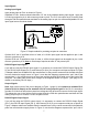
Power and Signal Connections Power can be supplied to your MC or VC Series controller through either the power jack or the 8 pin Mini-DIN connector as shown in Figure 1. Power may also be supplied through an AC to DC adapter which converts line AC power to DC voltage and current as specified below. The power jack accepts 2.1 mm female power plugs with positive centers.
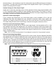
Input Signals Analog Input Signal Apply analog input to Pin 4 as shown in Figure 1. Standard 0-5 Vdc: Unless ordered otherwise, 0-5 Vdc is the standard analog input signal. Apply the 0-5 Vdc input signal to pin 4, with common ground on pin 8. The 5.12 Vdc output on pin 2 can be wired through a 50K ohm potentiometer and back to the analog input on pin 4 to create an adjustable 0-5 Vdc input signal source as shown below. 8 0-5 Vdc 6 7 3 4 5 2 1 5.12 Vdc 50 KOhm Potentiometer Figure 2.
the connections, i.e. the connector on top of the meter and the physical DB-9 serial port on the back of the computer. The cable ends will be mirror images of the diagram shown in Figure 3. (See page 21 for details on accessing RS-232 output.) Standard Voltage (0-5 Vdc) Output Signal All MC and VC series flow controllers have a 0-5 Vdc (optional 0-10 Vdc) output signal available on Pin 6. This is generally available in addition to other optionally ordered outputs. This voltage is usually in the range of 0.
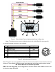
Purple (Ground) Red Yellow Unit A Purple Red Yellow Unit B Purple Red Yellow Unit C 2 2 3 4 1 5 3 5 9 7 8 6 Female Serial Cable Front Figure 4. Typical Multiple Device (Addressable) Wiring Configuration Note: The easiest way to connect multiple devices is with a Multi-Drop Box (see page 46).
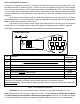
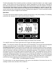
The MC Series Mass Flow Controller provides a multitude of useful flow data in one simple, rugged device. The MC Series can have several screen “modes” depending on how the device is ordered. All MC Series controllers have a default Main Mode, Select Menu Mode, Control Set Up Mode, Gas Select Mode (the Gas Select Mode may not be available on controllers calibrated for a custom gas or blend), Communication Select Mode, Manufacturer Data Mode and a Miscellaneous Mode.
Gas Temperature: The MC Series flow controllers utilize a temperature sensor to measure the line temperature of the gas flow being monitored. The temperature is displayed in engineering units of degrees Celsius (°C). The flow controllers use the temperature of the gas in the calculation of the mass flow rate. This parameter is located in the upper middle portion of the display under “°C”. This parameter can be moved to the primary display by pushing the top center button above “°C”.
Control Setup Mode The Control Setup Mode is accessed by pressing the center button above “Control Setup” on the Select Menu display (Fig.7) This mode allows the user to set up most parameters commonly associated with PID control. Alicat Scientific flow controllers allow the user to select how the set-point is to be conveyed to the controller, what that set-point is if control is local, and what the Proportional and Differential terms of the PID control loop will be.
Loop—The selection of what variable to close the loop on is a feature unique to these mass flow controllers. When the mass flow controller is supplied with the control valve upstream of the electronics portion of the system, the unit can be set to control on outlet pressure (absolute pressures only) or volumetric flow rate, instead of mass flow rate. Repeatedly pressing the button adjacent to the word “Loop” on the control setup screen will change what variable is controlled.
Gas Select Mode The gas select mode is accessed by pressing the button above “Gas Select” on the Select Menu display. The screen will appear as shown in Figure 9. PgUP H2 He >N2 N2O Ne O2 UP PgDWN Main Hydrogen Helium Nitrogen Nitrous Oxide Neon Oxygen DOWN Gas Figure 9. Gas Select Display The selected gas is displayed on the default main mode screen as shown in Figure 6, and is indicated by the arrow in the Gas Select Mode screen in Figure 9.
Communication Select Mode The Communication Select mode is accessed by pressing the button below “Comm. RS-232” on the Select Menu display. The screen will appear as shown in Figure 10. Select > Unit ID (A).....A Baud (19200)....19200 Data Rate......Fast UP DOWN Comm. RS-232 Figure 10. Communication Select Display Unit ID – Valid unit identifiers are letters A-Z and @ (see Note below).
Manufacturer Data Mode “Manufacturer Data” is accessed by pressing the “Mfg. Data” button on the Select Menu display (Figure 11). The “Mfg 1” display shows the name and telephone number of the manufacturer. The“Mfg 2” display shows important information about your flow meter including the model number, serial number, and date of manufacture. Main Alicat Scientific, Inc. Ph 520-290-6060 Fax 520-290-0109 Mfg 1 Main Model MC-10SLPM-D Serial No 27117 Date Mfg.11/07/2007 Calibrated By.
Select Main LCD Contrast(10) . PVM DBand (0.5% FS) PRESS Avg (008) . . . FLOW Avg (100) . . . . 10 > UP DOWN 008 100 Misc Figure 12. Miscellaneous Display LCD Contrast: The Liquid Crystal Display Contrast can be adjusted between 0 and 30 with zero being the lightest contrast and 30 being the darkest contrast. To change the contrast, press the “Select” button in the upper left hand corner of the display until the cursor arrow is in front of the words “LCD Contrast (X)”.
VC Series Volumetric Flow Controller Operation The VC Series can have several screen “modes” depending on how the device is ordered. All VC Series controllers have a default Main Mode, Select Menu Mode, Control Setup Mode, Gas Select Mode (the Gas Select Mode may not be available on meters calibrated for a custom gas or blend), Communication Select Mode, Manufacturer Data Mode and Miscellaneous Mode. In addition, your device may have been ordered with the optional Totalizing Mode (page 43).
Select Menu Mode Pushing “Mode” once will bring up the “Select Menu” display (Figure 7, page 11). Push the button nearest your selection to go to the corresponding screen. Push “Mode” again to return to the Main Mode display. (Note: If your controller was ordered with Totalizing Mode option (page 43), pushing the “Mode” button once will bring up the “Totalizing Mode” display. Pushing “Mode” a second time will bring up the “Select Menu” display.
Serial refers to a remote digital RS-232 set-point applied via a serial connection to a computer or PLC as described in the Installation and RS-232 sections of this manual. CAUTION! Never leave a Controller with any non-zero set-point if no pressure is available to make flow. The controller will apply full power to the valve in an attempt to reach the set-point. When there is no flow, this can make the valve very HOT! Local refers to a set-point applied directly at the controller.
Communication Select Mode The Communication Select mode is accessed by pressing the button below “Comm. RS-232” on the Select Menu display. Please see page 14 for Communication Select mode instructions. Manufacturer Data Mode “Manufacturer Data” is accessed by pressing the “Mfg. Data” button on the Select Menu display (Figure 7, page 11). The “Mfg 1” display shows the name and telephone number of the manufacturer.
Once you have established communication with the unit and have a stream of information filling your screen: 1. Type *@=A followed by “Enter” (or using the RS-232 communcation select menu, select A as identifier and exit the screen) to stop the streaming mode of information. Note that the flow of information will not stop while you are typing and you will not be able to read what you have typed. Also, the unit does not accept a backspace or delete in the line so it must be typed correctly.
The computer will respond by reading the current value for register 21 between 0-65535. It is good practice to write this value down so you can return to the factory settings if necessary. Enter the value you wish to try by writing the new value to register 21. For example, if you wished to try a “P” term of 220, you would type *W21=220 followed by “Enter” where the bold number denotes the new value. The computer will respond to the new value by confirming that 21=220.
Gas Select – The selected gas can be changed via RS-232 input. To change the selected gas, enter the following commands: In Streaming Mode: $$# In Polling Mode: Address$$# (e.g. B$$#) Where # is the number of the gas selected from the table below.
Collecting Data: The RS-232 output updates to the screen many times per second. Very short-term events can be captured simply by disconnecting (there are two telephone symbol icons at the top of the HyperTerminal® screen for disconnecting and connecting) immediately after the event in question. The scroll bar can be driven up to the event and all of the data associated with the event can be selected, copied, and pasted into Microsoft® Excel® or other spreadsheet program as described below.
Sending a Simple Script File to HyperTerminal® It is sometimes desirable to capture data for an extended period of time. Standard streaming mode information is useful for short term events, however, when capturing data for an extended period of time, the amount of data and thus the file size can become too large very quickly. Without any special programming skills, the user can use HyperTerminal® and a text editing program such as Microsoft® Word® to capture text at user defined intervals. 1.
Operating Principle All M and V Series Gas Flow Meters (and MC and VC Series Gas Flow Controllers) are based on the accurate measurement of volumetric flow. The volumetric flow rate is determined by creating a pressure drop across a unique internal restriction, known as a Laminar Flow Element (LFE), and measuring differential pressure across it.
Other Gases: M Series Flow Meters can easily be used to measure the flow rate of gases other than those listed as long as “non-corrosive” gas compatibility is observed. For example, a flow meter that has been set for air can be used to measure the flow of argon. The conversion factor needed for measuring the flow of different gases is linear and is simply determined by the ratio of the absolute viscosity of the gases.
Once the corrected mass flow rate at standard conditions has been determined and the density at standard conditions is known (see the density table at the back of this manual), a true mass flow can be calculated as detailed in the following example: Mass Flow Meter Reading = 250 SCCM (Standard Cubic Centimeters/Minute) Gas: Helium Gas Density at 25C and 14.696 PSIA = .16353 grams/Liter True Mass Flow = (Mass Flow Meter Reading) X (Gas Density) True Mass Flow = (250 CC/min) X (1 Liter / 1000 CC) X (.
This reduces to: Pa Va / Za Ta = Ps Vs / Zs Ts , eliminating R and n. Alicat mass flow meters model gas flows based upon the non-ideal gas characteristics of the calibrated gas. The flow corrections are normally made to 25 C and 14.696 PSIA and the compressibility factor of the gas under those conditions. This allows the user to multiply the mass flow rate by the density of the real gas at those standard conditions to get the mass flow rate in grams per minute.
Gas Number Short Form Long Form 0 1 2 3 4 5 6 7 8 9 10 11 12 13 14 15 16 17 18 19 20 21 22 23 24 25 26 Air Ar CH4 CO CO2 C2H6 H2 He N2 N2O Ne O2 C3H8 n-C4H10 C2H2 C2H4 i-C4H10 Kr Xe SF6 C-25 C-10 C-8 C-2 C-75 A-75 A-25 27 A1025 28 Star29 29 P-5 Air Argon Methane Carbon Monoxide Carbon Dioxide Ethane Hydrogen Helium Nitrogen Nitrous Oxide Neon Oxygen Propane normal-Butane Acetylene Ethylene iso-Butane Krypton Xenon Sulfur Hexafluoride 75% Argon / 25% CO2 90% Argon / 10% CO2 92% Argon / 8% CO2 98%
Gas Number Short Form Long Form 0 1 2 3 4 5 6 7 8 9 10 11 12 13 14 15 16 17 18 19 20 21 22 23 24 25 26 Air Ar CH4 CO CO2 C2H6 H2 He N2 N2O Ne O2 C3H8 n-C4H10 C2H2 C2H4 i-C4H10 Kr Xe SF6 C-25 C-10 C-8 C-2 C-75 A-75 A-25 27 A1025 28 Star29 29 P-5 Air Argon Methane Carbon Monoxide Carbon Dioxide Ethane Hydrogen Helium Nitrogen Nitrous Oxide Neon Oxygen Propane normal-Butane Acetylene Ethylene iso-Butane Krypton Xenon Sulfur Hexafluoride 75% Argon / 25% CO2 90% Argon / 10% CO2 92% Argon / 8% CO2 98%
Volumetric Flow Meters and Controllers Under Pressure V and VC Series Volumetric Flow Meters/Controllers are intended for use in low pressure applications. This is because an accurate measurement of the volumetric flow rate by means of differential pressure requires the flow at the differential pressure sensor to be in a laminar state. The state of the flow is quantified by what is known as the Reynolds Number.
TROUBLESHOOTING Display does not come on or is weak. Check power and ground connections. Flow reading is approximately fixed either near zero or near full scale regardless of actual line flow. Differential pressure sensor may be damaged. Avoid installations that can subject sensor to pressure drops in excess of 10 PSID. A common cause of this problem is instantaneous application of high‑pressure gas as from a snap acting solenoid valve upstream of the meter.
RS-232 Serial Communications is not responding. Check that your meter is powered and connected properly. Be sure that the port on the computer to which the meter is connected is active. Confirm that the port settings are correct per the RS-232 instructions in this manual (Check the RS-232 communications select screen for current meter readings). Close Hyperterminal® and reopen it. Reboot your PC. Slower response than specified.
Technical Data for Micro-Flow and Ultra-Low Flow Mass & Volumetric Flow Controllers 0 to 0.5SCCM Full Scale through 0 to 50SCCM Full Scale Specification Accuracy High Accuracy Option Repeatability Operating Range Typical Response Time Standard Conditions (STP) Operating Temperature Zero Shift Span Shift Humidity Range Controllable Flow Rate Maximum Pressure Mass Controller Volumetric Controller Description At calibration conditions after tare ± (0.8% of Reading + 0.
Technical Data for Low Flow Mass & Volumetric Flow Controllers 0 to 100SCCM Full Scale through 0 to 20SLPM Full Scale Specification Accuracy High Accuracy Option Repeatability Operating Range Typical Response Time Standard Conditions (STP) Operating Temperature Zero Shift Span Shift Humidity Range Controllable Flow Rate Maximum Pressure Mass Controller Volumetric Controller Description At calibration conditions after tare ± (0.8% of Reading + 0.2% of Full Scale) At calibration conditions after tare ± (0.
Technical Data for Moderate Flow Mass & Volumetric Flow Controllers 0 to 50SLPM Full Scale through 0 to 100SLPM Full Scale Specification Accuracy High Accuracy Option Repeatability Operating Range Typical Response Time Standard Conditions (STP) Operating Temperature Zero Shift Span Shift Humidity Range Controllable Flow Rate Maximum Pressure Mass Controller Volumetric Controller Description At calibration conditions after tare ± (0.8% of Reading + 0.
Technical Data for High Flow Mass & Volumetric Flow Controllers 0 to 250SLPM Full Scale through 0 to 1500SLPM Full Scale Specification Accuracy High Accuracy Option Repeatability Operating Range Typical Response Time Standard Conditions (STP) Operating Temperature Zero Shift Span Shift Humidity Range Controllable Flow Rate Maximum Pressure Mass Controller Volumetric Controller Description At calibration conditions after tare ± (0.8% of Reading + 0.
MC & VC Series: 0 - 0.5SCCM 0 - 1SCCM 0 - 2SCCM 0 - 5SCCM 0 - 10SCCM 0 - 20SCCM 0 - 50SCCM No. Rev. No.
MC & VC Series: 0 - 50SLPM 0 - 100SLPM
MCR & VCR Series: 0 - 500SLPM 0 - 1000SLPM 0 - 1500SLPM Rev. No.
Option: Totalizing Mode 16 Series Flow Meters and Controllers can be purchased with the Totalizing Mode option. This option adds an additional mode screen that displays the total flow (normally in the units of the main flow screen) that has passed through the meter or controller since the last time the totalizer was cleared. The Totalizing Mode screen shown below is accessed by pushing the “MODE” button until the label over it reads “Total”.
Alicat Portable Meters and Gauges Alicat Portable Flow Meters and Gauges use a common 9 Volt battery located in the top section of your meter. Output signals from the flow meter are passed through the female connector on top of the flow meter. Turn the switch on top of the flow meter “off” when the meter is not in use. Normal (9V alkaline) battery life is approximately 8 hours (30-40 hours with a 9V-lithium battery), however many factors can affect this. Replace the battery as often as required.
Option: Local Set-Point Module The Local Set-Point Module (LSPM) is designed to provide the user with a simple “turn of the dial” method of changing a flow or pressure controller set-point. The LSPM features a set-point control dial, a digital LED display which can be set to show either the set-point or the actual process measurement, and a tracking alarm LED which glows red whenever the actual process measurement deviates from the set-point by more than 2% of full scale.
Option: Remote Electronics for High Line or Gas Temperatures Some applications involve operating temperatures outside the standard Alicat device specifications. A solution using remote electronics is available. (This option is not applicable to liquid devices.) The flow body’s components are minimized to only the required sensors. The flow data is sent to the microprocessor electronics up to 6 feet away from the sensor package.
Accessory: Flow Vision™ SC Software Devices Scripts Data Logs Charts Terminals Flow Vision™ SC is an intuitive software interface to help your test cycles run smoother and shorten your engineering time! Flow Vision™ SC lets you connect to and communicate with multiple Alicat units simultaneously. Now you can view virtual displays, control tabs, charts and data lines from every connected Alicat device on the same screen.
Accessories Part Number FLOWVISIONSC BB-9 PCASE DC-61 DC-251 DC-301 DC-501 DC-751 DC-6RT DC-62 DC-252 DC-502 DC-602 MD8DB9 IC10 IC10-18G IC20 IC24-18G IC50 PVPS24U LSPM RS485-KIT REMOTE RD Description Flow Vision™ SC software for interface with all Alicat instruments Multi-Drop Box Industrial carry and storage case for portable meters/gauges 8 Pin Male Mini-DIN connector cable, single ended, 6 foot length 8 Pin Male Mini-DIN connector cable, single ended, 25 foot length 8 Pin Male Mini-DIN connector cable,
DB15 Pin-Outs If your Alicat Instrument was ordered with a DB15 connection, please be sure to reference the appropriate pin-out diagram. DB15 Pin-Out Pin Number 2 5 8 9 11 13 15 9 8 5 2 Function Signal Out Supply Set-Point Ground Secondary Out RS-232 Receive RS-232 Send 11 13 15 Note: The above pin-out is correct for units with a DB15 pin‑out. If your unit is marked DB15H or DB15K, you must use the correct pin-out (as shown on the following page).
DB15 Pin-Outs If your Alicat Instrument was ordered with a DB15 connection, please be sure to reference the appropriate pin-out diagram.