Operating Manual 16 Series Portable Calibration Unit Innovative Flow and Pressure Solutions
Notice: Alicat Scientific, Inc. reserves the right to make any changes and improvements to the products described in this manual at any time and without notice. This manual is copyrighted. This document may not, in whole or in part, be copied, reproduced, translated, or converted to any electronic medium or machine readable form, for commercial purposes, without prior written consent from the copyright holder.
Table of Contents Connecting the PCU Operating the PCU Main Mode Tare Gas Absolute Pressure Gas Temperature Volumetric Flow Rate Mass Flow Rate Flashing Error Message Select Menu Mode Gas Select Mode Communication Select Mode Unit ID Baud Data Rate Manufacturer Data Mode Miscellaneous Mode LCD Contrast Display Zero Deadband Pressure Averaging Flow Averaging RS-232 Output and Input Configuring HyperTerminal® Tare Collecting Data Data Format Gas Select Sending a Simple Script File to HyperTerminal® Operating
Table of Contents Additional Information Flow Conversion Table Option: Totalizing Mode Screen Table of Figures Figure 1. PCU Controls and Connections Figure 2. Main Mode Display Figure 3. Select Menu Display Figure 4. Gas Select Display Figure 5. Communication Select Display Figure 6. Manufacturer Data Displays Figure 7.
Portable Calibration Unit Thank you for purchasing an Alicat Scientific Portable Calibration Unit (PCU). Please take the time to find and read the information contained in this manual. This will help to ensure that you get the best possible service from your instrument. The Alicat Scientific Portable Calibration Unit (PCU) is designed to accurately measure gas flow rates of common gases with three separate flow meters with ranges determined by the end user’s needs.
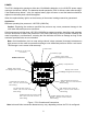
POWER The PCU is designed to operate on either two 9 Volt Alkaline batteries or via a 9-20VDC power supply running at a minimum 100mA. The batteries should operate the PCU for 8 hours under normal usage. If the batteries drop below 7 volts, the replace battery light will come on and the batteries should be replaced or alternate power should be applied. When the replace battery light is on the accuracy of the meters’ readings cannot be guaranteed.
Operating the PCU The meter for each flow range on the PCU is controlled by its own set of Display/Control electronics located above the inlet and outlet ports of each flow range. The PCU meters can have several screen “modes” depending on how the device is ordered.
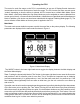
Once zeroed the PCU can now be used to check the calibration of other mass flow meters. Providing there are no leaks in the lines, the PCU can be used to check another mass flow meter either upstream or downstream of the PCU. Note: The PCU cannot be used to directly check volumetric flow meters (such as rotameters) because the density of the gas changes with the pressure drop present in all systems.
Select Menu Mode Pushing “Mode” once will bring up the “Select Menu” display. Push the button nearest your selection to go to the corresponding screen. Push “Mode” again to return to the Main Mode display. (Note: If your meter was ordered with Totalizing Mode option (page 26), pushing the “Mode” button once will bring up the “Totalizing Mode” display. Pushing “Mode” a second time will bring up the “Select Menu” display.) Gas Select Misc SELECT MENU Comm. RS-232 Gas Select Mode Mfg.
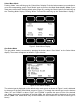
Communication Select The Communication Select mode is accessed by pressing the button below “Comm. RS-232” on the Select Menu display. The screen will appear as shown in Figure 5 below. Select > Unit ID (A).....A Baud (19200)....19200 Data Rate......Fast UP DOWN Comm. RS-232 Figure 5. Communication Select Display Unit ID – Valid unit identifiers are letters A-Z and @ (see Note below).
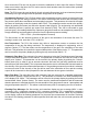
Manufacturer Data “Manufacturer Data” is accessed by pressing the “Mfg. Data” button on the Select Menu display (Figure 3). The “Mfg 1” display shows the name and telephone number of the manufacturer. The“Mfg 2” display shows important information about your flow meter including the model number, serial number, and date of manufacture. Main Alicat Scientific, Inc. Ph 520-290-6060 Fax 520-290-0109 Mfg 1 Main Model M-10SLPM-D Serial No 27117 Date Mfg.11/07/2009 Calibrated By.
Select Main LCD Contrast(10) . PVM DBand (0.5% FS) PRESS Avg (008) . . . FLOW Avg (100) . . . . 10 > UP DOWN 008 100 Misc Figure 7. Miscellaneous Display LCD Contrast: The Liquid Crystal Display Contrast can be adjusted between 0 and 30 with zero being the lightest contrast and 30 being the darkest contrast. To change the contrast, press the “Select” button in the upper left hand corner of the display until the cursor arrow is in front of the words “LCD Contrast (X)”.
RS-232 Output and Input Connect the male RS-232 DB9 port (See Fig. 1) of the PCU to the serial port of your computer or data logger. This will normally require a female/female DB9 cable (included). One of the most common ways to access the RS-232 output from your PCU is through a simple terminal program. Open your Hyperterminal RS-232 terminal program (installed under the “Accessories” menu on all Microsoft Windows operating systems). Select “Properties” from the file menu.
RS-232 Output and Input Configuring HyperTerminal®: 1. Open your HyperTerminal® RS-232 terminal program (installed under the “Accessories” menu on all Microsoft Windows operating systems). 2. Select “Properties” from the file menu. 3. Click on the “Configure” button under the “Connect To” tab. Be sure the program is set for: 19,200 baud (or matches the baud rate selected in the RS-232 communications menu on the meter) and an 8-N-1-None (8 Data Bits, No Parity, 1 Stop Bit, and no Flow Control) protocol. 4.
Data Format: The data stream on the screen represents the flow parameters of the main mode in the units shown on the display. When the queried the window will fill with 6 columns of data representing the range (L=Low, M=Medium, H=High), absolute pressure, temperature, volumetric flow, mass flow, and selected gas respectively. Pressure units are PSIA, temperature units are Degrees C, volumetric flow units are Liters Per Minute, and mass flow units are Standard Liters Per Minute.
Gas Select – The selected gas can be changed via RS-232 input. To change the selected gas, enter the following commands: In Polling Mode: Address$$# (e.g. B$$#) Where # is the number of the gas selected from the table below.
Sending a Simple Script File to HyperTerminal® It is sometimes desirable to capture data for an extended period of time. Standard streaming mode information is useful for short term events, however, when capturing data for an extended period of time, the amount of data and thus the file size can become too large very quickly. Without any special programming skills, the user can use HyperTerminal and a text editing program such as Microsoft Word to capture text at user defined intervals. 1.
Operating Principle All PCU Gas Flow Meters are based on the accurate measurement of volumetric flow. The volumetric flow rate is determined by creating a pressure drop across a unique internal restriction, known as a Laminar Flow Element (LFE), and measuring differential pressure across it.
Other Gases: PCU Flow Meters can easily be used to measure the flow rate of gases other than those listed as long as “non-corrosive” gas compatibility is observed. For example, a flow meter that has been set for air can be used to measure the flow of argon. The conversion factor needed for measuring the flow of different gases is linear and is simply determined by the ratio of the absolute viscosity of the gases.
Once the corrected mass flow rate at standard conditions has been determined and the density at standard conditions is known (see the density table at the back of this manual), a true mass flow can be calculated as detailed in the following example: Mass Flow Meter Reading = 250 SCCM (Standard Cubic Centimeters/Minute) Gas: Helium Gas Density at 25C and 14.696 PSIA = .16353 grams/Liter True Mass Flow = (Mass Flow Meter Reading) X (Gas Density) True Mass Flow = (250 CC/min) X (1 Liter / 1000 CC) X (.
This reduces to: Pa Va / Za Ta = Ps Vs / Zs Ts , eliminating R and n. Alicat mass flow meters model gas flows based upon the non-ideal gas characteristics of the calibrated gas. The flow corrections are normally made to 25 C and 14.696 PSIA and the compressibility factor of the gas under those conditions. This allows the user to multiply the mass flow rate by the density of the real gas at those standard conditions to get the mass flow rate in grams per minute.
Gas Number Short Form Long Form 0 1 2 3 4 5 6 7 8 9 10 11 12 13 14 15 16 17 18 19 20 21 22 23 24 25 26 Air Ar CH4 CO CO2 C2H6 H2 He N2 N2O Ne O2 C3H8 n-C4H10 C2H2 C2H4 i-C4H10 Kr Xe SF6 C-25 C-10 C-8 C-2 C-75 A-75 A-25 27 A1025 28 Star29 29 P-5 Air Argon Methane Carbon Monoxide Carbon Dioxide Ethane Hydrogen Helium Nitrogen Nitrous Oxide Neon Oxygen Propane normal-Butane Acetylene Ethylene iso-Butane Krypton Xenon Sulfur Hexafluoride 75% Argon / 25% CO2 90% Argon / 10% CO2 92% Argon / 8% CO2 98%
Gas Number Short Form Long Form 0 1 2 3 4 5 6 7 8 9 10 11 12 13 14 15 16 17 18 19 20 21 22 23 24 25 26 Air Ar CH4 CO CO2 C2H6 H2 He N2 N2O Ne O2 C3H8 n-C4H10 C2H2 C2H4 i-C4H10 Kr Xe SF6 C-25 C-10 C-8 C-2 C-75 A-75 A-25 27 A1025 28 Star29 29 P-5 Air Argon Methane Carbon Monoxide Carbon Dioxide Ethane Hydrogen Helium Nitrogen Nitrous Oxide Neon Oxygen Propane normal-Butane Acetylene Ethylene iso-Butane Krypton Xenon Sulfur Hexafluoride 75% Argon / 25% CO2 90% Argon / 10% CO2 92% Argon / 8% CO2 98%
TROUBLESHOOTING Display does not come on or is weak. Recharge the battery. Flow reading is approximately fixed either near zero or near full scale regardless of actual line flow. Differential pressure sensor may be damaged. Avoid installations that can subject sensor to pressure drops in excess of 10 PSID. A common cause of this problem is instantaneous application of highpressure gas as from a snap acting solenoid valve upstream of the meter.
Slower response than specified. PCU meters feature an RS-232 programmable Geometric Running Average (GRA). Depending on the full scale range of the meter, it may have the GRA set to enhance the stability/readability of the display, which would result in slower perceived response time. If you require the fastest possible response time, please consult the factory for written instructions on adjusting the GRA. Jumps to zero at low flow. PCU meters feature an RS-232 programmable zero deadband.
Technical Data for the Alicat Portable Calibration Unit (PCU) The following specifications are for the standard configuration of the device. Please contact us or visit www.alicatscientific.com for customization details, application notes, etc. Basic Specification PCU Meters Accuracy Repeatability Operating Range Typical Response Time Standard Conditions (STP) Operating Temperature Zero Shift Span Shift Humidity Range Flow Rate Maximum Pressure Input /Output Signal Standard ± (0.4% of Reading ±0.
Option: Totalizing Mode Screen PCU Meters can be purchased with the Totalizing Mode option. This option adds an additional mode screen that displays the total flow (normally in the units of the main flow screen) that has passed through the meter or controller since the last time the totalizer was cleared. The Totalizing Mode screen shown below is accessed by pushing the “MODE” button until the label over it reads “Total”.