
User guide
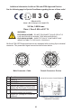

Additional Information for Alicat CSA and ATEX Approved Devices
See the following page for Special Conditions regarding the use of these units!
EEx nA IIC T4
Class I, Div. 2 Group A, B, C and D T4
24 Vdc, 0.800A max
Class I, Zone 2 AEx nA IIC T4
WARNINGS:
EXPLOSION HAZARD – DO NOT DISCONNECT WHILE CIRCUIT IS
LIVE UNLESS AREA IS KNOWN TO BE NON-HAZARDOUS.
EXPLOSION HAZARD – SUBSTITUTION OF COMPONENTS MAY
IMPAIR SUITABILITY FOR CLASS I, DIVISION 2.
II 3 G
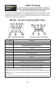
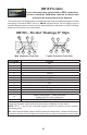
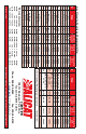
Industrial Connector Overall Clearance
Minimum
Removal
Clearance
Min. Clearance w/
Cable Bend
2.537
1.817
1.602
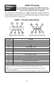
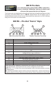
All Alicat CSA / ATEX approved devices are equipped with a locking 6 pin industrial
connector. The power and signal connections are shown below.
Clearance Requirements for
Industrial Connector
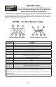
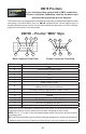
Pin Function
1 Power In ( + )
2 RS-232TX
3 RS-232RX
4 Remote Tare Meters (Ground to Tare)
Analog Set-Point Input (Controllers)
5 Ground (common for power,
communications and signals)
6 Signal Out (Voltage or Current as
ordered)
520-290-6060 Ph. 520-290-0109 Fax
7641 N Business Park Dr. Tucson, AZ 85743
Rev. No. Description Date
1
6
5
4
3
2
520-290-6060 Ph. 520-290-0109 Fax
7641 N Business Park Dr. Tucson, AZ 85743
Rev. No. Description Date
1
6
5
4
3
2
Male Connector: Cable Female Connector: Device