Local Set Point Module Operating Bulletin 1
Notice: The manufacturer reserves the right to make any changes and improvements to the products described in this manual at any time and without notice. This manual is copyrighted. This document may not, in whole or in part, be copied, reproduced, translated, or converted to any electronic medium or machine readable form, for commercial purposes, without prior written consent from the copyright holder.
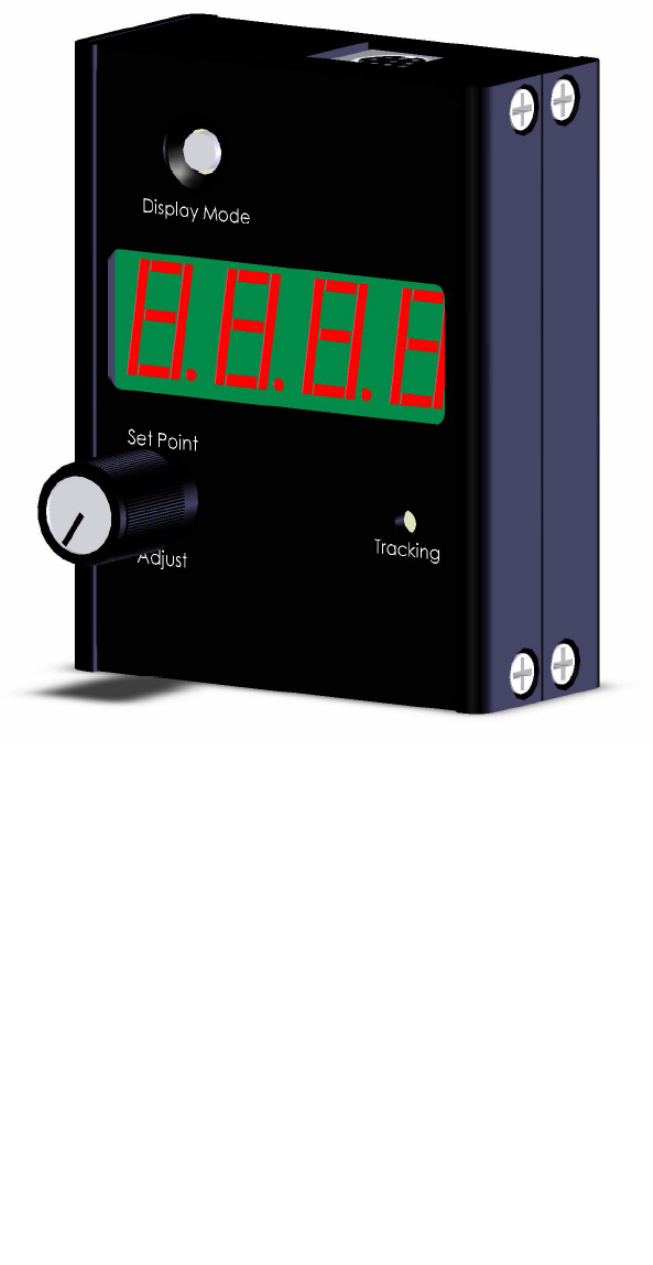
INTRODUCTION: The Local Set Point Module (LSPM) is designed to provide a simple method to adjust and monitor the set point to your flow controller. It utilizes a convenient one turn twist knob, a versatile LED display, and a set point tracking alarm LED in a simple remote mountable package. The LSPM reads the actual output signal, and can display the output parameter as well as the set point.
AC/DC Adapter Jack 1 3 2 4 6 7 5 8 Pin Function DC-61 (optional) Color Code 1 2 3 4 5 6 7 8 4-20mA Output Signal 5.12 Vdc or Auxiliary Output RS-232 Input Signal Set Point In RS-232 Output Signal 0-5 Vdc (or 0-10 Vdc) Output Signal Power In Ground (common) Black Brown Red Orange Yellow Green Blue Purple CAUTION: DO NOT CONNECT POWER TO PINS DAMAGE CAN OCCUR! 1 THROUGH Figure 1.
OPERATION: Display Mode Button: The LSPM display has several modes which are set via the Display Mode button. Pushing the button once will set the display menu cycle into operation. Pushing the button while the desired parameter is on the display will select that parameter. If the selected parameter has a sub menu, the sub menu will cycle until a menu item is selected by pushing the button while the sub menu item is on the display. Cycle rate is approximately 1 per second.
Tracking LED: The tracking LED is intended to alert the user whenever the actual process variable deviates from the set point by more than 2% of full scale. The tracking LED is always on whenever the LSPM has power and operates as follows: Green Red Process variable is within +/- 2% of Set Point Process variable is not within +/- 2% of Set Point It is common for the LED to show red during a change in set point.
Figure 4.
2.992 1.050 2.375 .670 Figure 5.