
Instruction manual

A
lfaSpid Rotator RAK1 http://Alfaspid.com http://www.hy-gain.com Page 8
Page 8 of 21
A
lfaSpid Rotator RAK1
http://Alfaspid.com http://www.hy-gain.com
Copyright
A
lfaRadio Ltd. 2002-2008
Since there are no mechanical limits in the rotator, it may be installed with the
antenna pointing in any direction. There is no reason to locate “TRUE NORTH”
until you are ready to calibrate the control box. Use the controller to position
the antenna to physically point north, then reset the controller as follows:
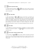
Turn the unit OFF. Then while holding the
button depressed turn control unit
back on. This will now show
on the display. The controller is now set for
North.
Display adjustment:
Press the button to cycle thru to the normal (i.e. blank) setting until you see the
display after P5 X, (X is the mode for computer interface) It will be blinking. The
display shows the normal degree reading i.e. 30 degrees, with the left or right arrows
the display reading can be changed with out turning the rotator in this mode, this
feature can be used if, for any reason, the direction of the antenna becomes incorrect.
This may be caused by antenna to mast slippage or incorrect initial alignment. The
Rotator to mast will not slip unless there is improper installation. See Heading Adjust
(numbers blinking) else where in this document.
IMPORTANT:
The
A
lfaSpid rotator is now set at the counter-clockwise end of its normal rotation
range. Normal rotation range is in a clockwise direction for 360 degrees.
From the reset position, you can rotate counter-clockwise an additional 180 degrees in
over-travel, as well 360 degrees clockwise, plus an additional 180 degrees into
clockwise over-travel.
Counter-clockwise over-travel is indicated by a steady dot above the over-travel icon.
Rotation past 359 degrees into the clockwise over-travel is indicated by a blinking
dot above the over-travel icon.
Technical Note:
Resettin
g
the Controller