
Instruction manual

A
lfaSpid Rotator RAK1 http://Alfaspid.com http://www.hy-gain.com Page 6
Page 6 of 21
A
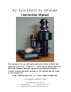
lfaSpid Rotator RAK1
http://Alfaspid.com http://www.hy-gain.com
Copyright
A
lfaRadio Ltd. 2002-2008
Wiring Connections
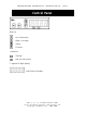
The rotator unit must be wired to the control unit with 4-wire cable. The gauge
of the 4-wire cable to connect the control unit to the rotator depends upon the
distance between rotator and controller. The wire for the impulse sensing may
be quite thin - #22 or similar, even for relatively long distances.
Length Gauge Motor
10 m (32') #18 (1.19 mm)
30 m (100') #16 (1.42 mm)
60 m (200') #14 (1.75 mm)
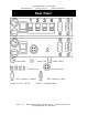
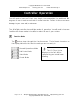
Remove cover from the motor body as shown and make connections as follows:
1 Motor Drive to 1 on controller terminal
2 Motor Drive to 2 on controller terminal
3 Impulse Sense to 3 on controller terminal
4 Impulse Sense to 4 on controller terminal
We suggest that the coax from the antenna be made with extra length to allow for the
“Over Travel” 720 degrees in total. You may wish to also allow for the coax to come
off the “South” side of the tower ( 180 degrees ). See diagram last page of this
manual.
CAUTION!:
Do not accidentally switch
the motor wires with the
impulse wires. Damage to the
control unit may occur!
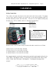
Installation