AlfaSpid Rotator and Controller Instruction Manual Copyright AlfaRadio Ltd 2002-2006 2006-01-09 www.alfaradio.ca 780.466.
AlfaSpid Rotator www.alfaradio.ca Page 2 Table of Contents Introduction......................................................................................... 3 Shipping Contents .............................................................................. 3 Technical Data ................................................................................... 3 Control Panel...................................................................................... 4 Rear Panel .................................
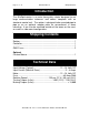
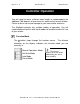
Page 3 of 21 www.alfaradio.ca AlfaSpid Rotator Introduction The AlfaSpid rotator is an extra heavy-duty rotator designed to run large communication antennas and comes complete with an electronic control unit. The rotator is designed to be mounted pipe to pipe or on an optional adaptor plate for conventional in tower mounting. It can also be mounted outside of the tower on the mast, or used in a side mount configuration. Shipping Contents Rotator...........................................................
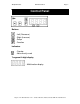
AlfaSpid Rotator www.alfaradio.ca Page 4 Control Front Panel Panel Buttons -Left (Decrease) -Right (Increase) -Setup -Function Indicators -Overlap -Not currently used 7 segment 4-digit display - Multifunction display Page 4 of 21 Alfa Radio Ltd. 11211 - 154 St.
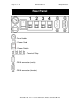
Page 5 of 21 www.alfaradio.ca AlfaSpid Rotator Rear Panel -Fuse Holder - Power Cord - Power Switch - Terminal Strip -DB-9 connector (male) -DB-9 connector (female) Alfa Radio Ltd. 11211 - 154 St.
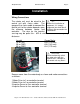
AlfaSpid Rotator www.alfaradio.ca Page 6 Installation Wiring Connections The rotator unit must be wired to the TIP: control unit with 4-wire cable. The Before final installation of gauge of the 4-wire cable to connect the equipment, it is strongly control unit to the rotator depends upon suggested you check out all the distance between rotator and functions and connections on a workbench. controller. The wire for the impulse sensing may be quite thin - #22 or similar, even for relatively long distances.
Page 7 of 21 www.alfaradio.ca AlfaSpid Rotator Bench Testing of Control Box The control box is normally expected to be operated from a 12 Volt DC supply; however it may be operated from other unregulated DC or AC sources as well. DC or AC voltage levels between 10 and 26 Volts capable of at least 5 Amps are acceptable, typically 12 or 14 Volts. The polarity of the power to the control box input leads is not critical for D.C.
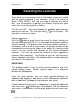
AlfaSpid Rotator www.alfaradio.ca Page 8 Resetting the Controller Since there are no mechanical limits in the rotator, it may be installed with the antenna pointing in any direction. There is no reason to locate “TRUE NORTH” until you are ready to calibrate the control box. Use the controller to position the antenna to physically point north, then reset the controller as follows: Turn the unit OFF. Then while holding the control unit back on. This will now show controller is now set for North.
Page 9 of 21 www.alfaradio.ca AlfaSpid Rotator Controller Operation Technical Note: You will need to leave sufficient coax length to accommodate the additional 180 degrees of over-travel on each end of normal rotation. Failure to do so can cause damage to your coax and/or antennas. The AlfaSpid controller has multiple modes of operation. You will need to become familiar with these modes to be able to make full use of your rotator. Function Mode The button steps through the function menus.
AlfaSpid Rotator www.alfaradio.ca Page 10 - Normal Operations Mode and buttons cause rotation In Normal Operations Mode, the as long as the buttons are pressed. Pressing while in normal operations mode will take you to setup mode. - Half Auto Mode buttons can be used to pre-select In Half Auto Mode, the and the desired beam heading. The heading displayed on the controller will rapidly change in the direction of desired rotation. Once the desired beam heading is shown on the display, release the key.
Page 11 of 21 www.alfaradio.ca AlfaSpid Rotator Setup Mode button steps through the setup menu. The display cycles The through each of the setup menu items.
AlfaSpid Rotator www.alfaradio.ca Page 12 - Programmable Low Limit The Programmable Low Limit is a user adjustable counterclockwise travel limit value. By increasing this value, the minimum counter-clockwise rotation travel can be restricted. Use the and buttons adjust the value. - Programmable Reset Value The Programmable Reset Value can be set to either 0 degrees, or 180 degrees. This is the beam heading set when a power on reset event is triggered.
Page 13 of 21 www.alfaradio.ca AlfaSpid Rotator - Program Simulation Program Simulation allows the user to set the serial communication protocol used by the rotator. When set to emulate another brand of rotator, the AlfaSpid will respond to commands, and send responses back to the computer as if it were the rotator brand selected. If your favourite software supports a rotator, chances are, the AlfaSpid will be able to interface to your software.
AlfaSpid Rotator www.alfaradio.ca Page 14 Mouse Controller (Optional) The optional mouse controller allows easy desktop access to the most commonly used front panel controls. These buttons are functionally equivalent to the corresponding front panel controls. - Left (Decrease) - Right (Increase) - Stop ( also the wheel between left and right buttons ) The mouse controller is a highly modified computer mouse. You can not use a regular mouse with the AlfaSpid rotator nor viceversa.
Page 15 of 21 www.alfaradio.ca AlfaSpid Rotator Alfa Radio Ltd. Trouble shouting tips Before contacting AlfaRadio Ltd. Please make the following tests:. The following are some trouble shouting tips, if for some reason your AlfaSpid will not operate correctly. It is important to confirm correct operation before installing on the tower. This will rule out any damage that may have been caused by the shipping company. Check the Limits - PH and PL settings and rule out overlap.
AlfaSpid Rotator www.alfaradio.ca Page 16 Be careful not to over wind your coax with the next test, as there will be no protection from over turning. Find a small 12 volts supply which will deliver 3 to 4 amps. ( a small 12 Volt battery will work just fine ) To confirm that the motor runs you may connect 12 volts D.C. to the lines that go to the motor, pins 1 and 2, it should turn. Reversing the 12 Volts D.C. should cause the motor to turn in the reverse direction.
Page 17 of 21 www.alfaradio.ca AlfaSpid Rotator Using the AlfaSpid Rotator with LONG Cable Distances By VE6JY Since the motor uses relatively low voltage DC, a combination of long cable runs and/or thinner than required cable may reduce the voltage at the motor to an unacceptably low value. It may turn in warm weather or light winds but the power will not be available to rotate under more severe conditions. While it is easy to say just use a heavier cable, this may be costly, impractical or both.
AlfaSpid Rotator www.alfaradio.ca Page 18 Relays chosen should be suitable for the proper coil voltage as well as appropriate current carrying capability. A relay capable of 5 to 10 amps DC is adequate. The diode in series with Relay K1 is any general purpose 1 amp style such as the 1N400x series. If the motor rotates incorrectly, simply reverse the leads to the motor or from the External DC Supply.
Page 19 of 21 www.alfaradio.ca AlfaSpid Rotator 12 MONTH LIMITED WARRANTY AlfaSpid Rotator and controller Alfa Radio Ltd. Warrants to the user, who originally purchased the product, that the product will be free from defects in material and workmanship for the following periods after such date of purchase: Material, 12 months : Workmanship, 12 months. Alfa Radio Ltd. will, at its option, repair or replace free of charge such defective products subject to the following conditions: 1.
AlfaSpid Rotator www.alfaradio.
Page 21 of 21 www.alfaradio.ca AlfaSpid Rotator Typical travel of the AlfaSpid Rotator Alfa Radio Ltd. 11211 - 154 St.