User's Guide Hammerfall® DSP System MADI ™ TotalMix 24 Bit / 96 kHz 9 ® SyncAlign ZLM ® ® SyncCheck ™ SteadyClock PCI Busmaster Digital I/O Card 64 Channels MADI Interface 24 Bit / 96 kHz Digital Audio Stereo Analog Monitoring 128 x 64 Matrix Router 2 x MIDI I/O MIDI embedded in MADI Quick Boot
General 1 2 3 4 5 6 Introduction ...............................................................6 Package Contents .....................................................6 System Requirements ..............................................6 Brief Description and Characteristics.....................6 Hardware Installation................................................7 Hardware – Connectors 6.1 External Connectors ..............................................7 6.2 Internal Connectors.........................
Driver Installation and Operation - Mac OS X 18 Driver and Flash Update 18.1 Driver Installation ................................................. 28 18.2 Driver Update....................................................... 28 18.3 Flash Update........................................................ 28 19 Configuring the HDSP MADI 19.1 Settings Dialog..................................................... 29 19.2 Settings Dialog – DDS ......................................... 31 19.
25 TotalMix: The Matrix 25.1 Overview ..............................................................56 25.2 Elements of the Matrix View ................................56 25.3 Usage...................................................................56 25.4 Advantages of the Matrix .....................................57 26 TotalMix Super-Features 26.1 ASIO Direct Monitoring (Windows only) ..............57 26.2 Selection and Group based Operation ................58 26.3 Copy Routings to other Channels ......
User's Guide HDSP MADI General User's Guide HDSP MADI © RME 5
1. Introduction Thank you for choosing the Hammerfall DSP MADI. This unique audio system is capable of transferring digital audio data directly into a computer, from any device equipped with a MADI interface. Installation is simple, even for the inexperienced user, thanks to the latest Plug and Play technology. The numerous unique features and well thought-out configuration dialog puts the Hammerfall DSP MADI at the very top of the range of digital audio interface cards.
5. Hardware Installation Before installing the PCI card, please make sure the computer is switched off and the power cable is disconnected from the mains supply. Inserting or removing a PCI card while the computer is in operation can cause irreparable damage to both motherboard and card! 1. Disconnect the power cord and all other cables from the computer. 2. Remove the computer's housing. Further information on how to do this can be obtained from your computer's instruction manual. 3.
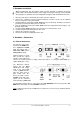
6.2 Internal Connectors X6 15-pin connector for the included HDSP MADI Expansion Board. X7 10-pin connector for a connection of the Time Code Option (TCO). Not functional. X1 No function. Used to program the card in the factory. Blue Jumper The internal blue jumper X4 allows to change the voltage level at the coaxial MADI output. In the lower position, the card generates 600 mVpp, according to the specification. Changing the jumper to the upper position, the output voltage is increased to 1.2 Vpp.
. Appendix RME news, driver updates and further product information are available on our website: http://www.rme-audio.com If you prefer to read the information off-line, you can browse through a complete copy of the RME website, found on the RME Driver CD (in the \rmeaudio.web directory). Manufacturer: IMM Elektronik GmbH, Leipziger Strasse 32, D-09648 Mittweida Trademarks All trademarks, registered or otherwise, are the property of their respective owners.
CE / FCC Compliance Statements CE This device has been tested and found to comply with the EN55022 class B and EN50082-1 norms for digital devices, according to the European Council directive on counterpart laws in the member states relating to electromagnetic compatibility (EMVG). FCC This device has been tested and found to comply with the requirements listed in FCC Regulations, part 15 for Class ‘B’ digital devices.
User's Guide HDSP MADI Driver Installation and Operation - Windows User's Guide HDSP MADI © RME 11
10. Driver and Firmware 10.1 Driver Installation After the HDSP MADI has been installed correctly (see 5. Hardware Installation), and the computer has been switched on, Windows will recognize the new hardware component and start its ‘Hardware Wizard’. Insert the RME Driver CD into your CD-ROM drive, and follow further instructions which appear on your computer screen. The driver files are located in the directory \MADI_AES32_w2k on the RME Driver CD.
10.4 Firmware Update The Flash Update Tool updates the HDSP MADI to the latest firmware version. It requires an already installed driver. Start the program madi_aes_fut.exe. The Flash Update Tool displays the current revision of the HDSP MADI, and whether it needs an update or not. If so, then please press the 'Update' button. A progress bar will indicate when the flash process is finished. The bar moves slowly first (program), then faster (verify).
Quick Boot All the card's settings described below are stored in a hardware memory, and are loaded immediately after a power-on of the computer. In clock mode Master even the last used sample rate is set. Directly after switching on the computer, a stable and predictable clock state is found at the HDSP MADI's outputs. This advanced technology completely eliminates disturbing noises and clock network problems during power-up or re-boot.
Input Status Displays the state of the current input signal: • • • • Channel format (64 or 56 channels) Frame format (48K or 96K) Sample rate (measured) Active input (optical or coaxial) Clock Mode The unit can be configured to use its internal clock source (Master), or the clock source predefined via Pref. Sync Ref (AutoSync). Pref. Sync Ref. Used to pre-select the desired clock source. If the selected source isn't available, the unit will change to the next available one.
DDS Activates all settings of this dialog. Value Shows the sample rate as adjusted in this dialog. The sample rate is defined by the basic setting (frequency), the multiplier, and the position of the activated fader. Frequency Sets a fixed basic sample rate, which can be modified by multiplier and fader. Freq. Multiplier Changes the basic sample rate into Single, Double oder Quad Speed mode. Coarse Fader for coarse modification of the basic sample rate. Click Active to activate it. Minimum step size 1 Hz.
The HDSP MADI's outstanding clock control allows for a synchronization of the output signal to the word clock's input signal not only at identical sample rates, but also at half, quarter, double and quad sample rates. A playback of 96 kHz can easily be synchronized via a 48 kHz word clock signal. SyncCheck If several digital devices are to be used simultaneously in a system, they not only have to operate with the same sample frequency but also be synchronous with each other.
12. Operation and Usage 12.1 Playback The HDSP system can play back audio data only in supported modes (channels, PCM) and formats (sample rate, bit resolution). Otherwise an error message appears (for example at 22 kHz and 8 bit). In the audio application being used, HDSP must be selected as output device. This can often be found in the Options, Preferences or Settings menus under Playback Device, Audio Devices, Audio etc. We strongly recommend switching off all system sounds (via >Control Panel /Sounds<).
12.2 DVD-Playback (AC-3/DTS) under MME AC-3 / DTS When using popular DVD software player like WinDVD and PowerDVD, their audio data stream can be sent to any AC-3/DTS capable receiver via the HDSP MADI. For this to work an output wave device has to be selected in >Control Panel/ Sounds and Multimedia/ Audio<. Also check 'use preferred device only'. You will notice that the DVD software's audio properties now allow to use 'SPDIF Out', 'Use SPDIF' or to 'activate SPDIF output'.
12.3 Low Latency under MME (Buffer Size Adjustment) Using Windows 95 or 98 the MME buffer size was nothing to worry about. Latencies below 46 ms were not possible. Meanwhile both computers and operating system have become much more powerful, and since Windows ME/2000/XP latencies far lower can be used. SAWStudio and Sonar allowed to use such low settings from the start. Sequoia was updated in version 5.91, WaveLab in version 3.04.
12.5 Recording Unlike analog soundcards which produce empty wave files (or noise) when no input signal is present, digital I/O cards always need a valid input signal to start recording. To take this into account, RME has included two unique features in the HDSP MADI: a comprehensive I/O signal status display (showing sample frequency, lock and sync status) in the Settings dialog, and the protective Safe Mode / Frequency function. If a 48 kHz signal is fed to the input and the application is set to 44.
13. Operation under ASIO 2.0 13.1 General Start the ASIO software and select ASIO Hammerfall DSP as the audio I/O device. The 'ASIO system control' button opens the HDSP's Settings dialog (see chapter 11, Configuration). Hammerfall DSP supports ASIO Direct Monitoring (ADM). Please note that currently Nuendo, Cubase and Logic either do not support ADM completely or error-free. Using emulated MIDI drivers often causes a drift and delay between audio and MIDI.
14. Operation under GSIF (Gigasampler Interface) Windows 2000/XP The GSIF interface of the HDSP MADI allows direct operation with Gigastudio, with up to 32* channels, 96 kHz and 24 bit. The new GSIF 2.0 is also supported with both audio and MIDI. Gigastudio requires a lot of the computer’s calculation power. An optimum performance is achieved with a stand-alone GSIF PC. However, when using the Hammerfall DSP, the latency is always the same as the one selected for ASIO operation.
15. Using multiple HDSP MADI / AES-32 The current driver supports operation of up to three HDSP MADI. Both HDSP MADI and HDSP AES-32 use the same driver, therefore can be used at the same time. Please note that only one TCO of one card can be used (of course). All units have to be in sync, i.e. have to receive valid sync information either via word clock or by using AutoSync and feeding synchronized signals.
17. Hotline – Troubleshooting 17.1 General The newest information can always be found on our website www.rme-audio.com, section FAQ, Latest Additions. The input signal cannot be monitored in real-time • ASIO Direct Monitoring has not been enabled, and/or monitoring has been disabled globally (for example in TotalMix). Playback works, but record doesn’t • Check that there is a valid signal at the input. If so, the current sample frequency is displayed in the Settings dialog.
17.2 Installation Hammerfall DSP is found in the Device Manager (>Settings/ Control Panel/ System<), category 'Sound-, Video- and Gamecontroller'. A double click on 'Hammerfall DSP MADI' starts the properties dialog. Choosing 'Resources' shows Interrupt and Memory Range. The newest information on hardware problems can always be found on our website www.rmeaudio.com, section FAQ, Hardware Alert: about incompatible hardware.
User's Guide HDSP MADI Driver Installation and Operation – Mac OS X User's Guide HDSP MADI © RME 27
18. Driver and Flash Update 18.1 Driver Installation First fit the card (see 5. Hardware Installation), then switch on the computer and install the drivers from the RME Driver CD. The driver file is located in the folder HDSP MADI AES32. Installation works automatically by a double-click on the file hdsp_madi_aes32.mpkg. RME recommends to download the latest driver version from the RME website! If done, the procedure is as follows: Double-click onto madi_aes_xx.gz to expand the archive file to madi_aes_xx.
19. Configuring the HDSP MADI 19.1 Settings Dialog Configuring the HDSP MADI is done via its own settings dialog. The panel 'Settings' can be opened by clicking on the hammer icon in the dock. The mixer of the HDSP MADI, TotalMix, can be opened by clicking on the mixer icon in the dock. The Hammerfall DSP’s hardware offers a number of helpful, well thought-of practical functions and options which affect how the card operates - it can be configured to suit many different requirements.
Safe Mode Input activates redundancy operation. If the current input signal fails, the other input will be used immediately, provided a valid signal is found there. Input also works as automatic input selection, in case only optical or coaxial is present as input signal. Clock Mode The unit can be configured to use its internal clock source (Master), or the clock source pre-defined via Pref. Sync Ref (AutoSync). Pref. Sync Ref. Used to pre-select the desired clock source.
19.2 Settings dialog - DDS Usually soundcards and audio interfaces generate their internal clock (master mode) by a quartz. Therefore the internal clock can be set to 44.1 kHz or 48 kHz, but not to a value in between. SteadyClock, RME's sensational Low Jitter Clock System, is based on a Direct Digital Synthesizer (DDS). This superior circuitry can generate nearly any frequency with highest precision.
Application examples DDS allows for a simultaneous change of speed and tune during record and playback. From alignment to other sources up to creative effects – everything is possible.. DDS allows to intentionally de-tune the complete DAW. This way, the DAW can match instruments which have a wrong or unchangeable tuning. DDS allows to define a specific sample rate. This feature can be is useful in case the system randomly changes the sample rate – for unknown reasons.
20. Mac OS X FAQ 20.1 Round about Driver Installation The driver with the file suffix gz provided by RME is a compressed TAR archive. TAR bundles multiple files and folders into one file, but does not save memory space nor download time. Both TAR and gz are supported natively by OS X, a double click on the file is all you need to do. Older browsers do not recognize gz as an archive, loading the file as a document. This results in a cryptic looking text within the browser window.
20.3 Supported Sample Rates RME's Mac OS X driver supports all sampling frequencies provided by the hardware. Besides 96 kHz this also includes 32 kHz and 64 kHz. But not every software will support all the hardware's sample rates. For example Spark does not display 32 kHz and 64 kHz. The hardware's capabilities can easily be verified in the Audio MIDI Setup. Select Audio devices under Properties of: and choose the Hammerfall DSP. A click on Format will list the supported sample frequencies.
21. Hotline – Troubleshooting The newest information can always be found on our website www.rme-audio.com, section Support, Macintosh OS. Playback works, but record doesn’t: • Check that there is a valid signal at the input. • Check whether the Hammerfall DSP has been selected as recording device in the audio application. • Check whether the sample frequency set in the audio application (‘Recording properties’ or similar) matches the input signal.
User's Guide HDSP MADI © RME
User's Guide HDSP MADI Connections and TotalMix User's Guide HDSP MADI © RME 37
22. Connections 22.1 Headphones HDSP MADI offers a hi-quality analog monitor output. The short circuit protected stereo line output provides high output level, low impedance, and is available via a 6.3 mm (1/4") TRS jack. Therefore it is also suitable for a direct use with headphones. The analog output is directly driven from the channels 63/64, in Double Speed mode with channels 33/34. Its output volume is controlled by the hardware output faders of channel 63/64 in TotalMix.
22.3 MIDI The HDSP MADI offers two MIDI I/O via 5-pin DIN connectors. The MIDI ports are added to the system by the driver. Using MIDI capable software, these ports can be accessed under the name MADI MIDI. Using more than one HDSP MADI, a consecutive number is added to the port name, like MADI MIDI In 1 (2) etc. The MIDI In port is available for both GSIF (GSIF-2 Low Latency) and standard MME MIDI simultaneously.
The received word clock signal can be distributed to other devices by using the word clock output. With this the usual T-adapter can be avoided, and the HDSP MADI operates as Signal Refresher. This kind of operation is highly recommended, because • • • • input and output are phase-locked and in phase (0°) to each other SteadyClock removes nearly all jitter from the input signal the exceptional input (1 Vpp sensitivity instead of the usual 2.
The actual end of these problems is offered by the SteadyClock technology of the HDSP MADI. Combining the advantages of modern and fastest digital technology with analog filter techniques, re-gaining a low jitter clock signal of 22 MHz from a slow word clock of 44.1 kHz is no problem anymore. Additionally, jitter on the input signal is highly rejected, so that even in real world usage the re-gained clock signal is of highest quality.
23.4 Operation The HDSP MADI's word clock input is active when Pref. Sync Ref in the Settings dialog has been set to Word Clock, the clock mode AutoSync has been activated, and a valid word clock signal is present. The signal at the BNC input can be Single, Double or Quad Speed, the HDSP automatically adapts to it. As soon as a valid signal is detected, the green LED at the bracket is lit, and the Settings dialog shows either Lock or Sync (see chapter 30.2).
24. TotalMix: Routing and Monitoring 24.1 Overview The HDSP MADI includes a powerful digital real-time mixer, the Hammerfall DSP mixer, based on RME’s unique, sample-rate independent TotalMix technology. It allows for practically unlimited mixing and routing operations, with all inputs and playback channels simultaneously, to any hardware outputs. Here are some typical applications for TotalMix: • Setting up delay-free submixes (headphone mixes).
User's Guide HDSP MADI © RME
24.2 The User Interface The visual design of the TotalMix mixer is a result of its capability to route hardware inputs and software playback channels to any hardware output. The HDSP MADI provides 64 input channels, 64 software playback channels, and 64 hardware output channels: 128 channels don't fit on the screen side by side, neither does such an arrangement provide a useful overview. The input channel should be placed above the corresponding output channel.
24.3 Elements of a Channel A single channel consists of various elements: Input channels and playback channels each have a mute and solo button. Below there is the panpot, realized as indicator bar (L/R) in order to save space. In the field below, the present level is displayed in RMS or Peak, being updated about every half a second. Overs (overload) are indicated here by an additional red dot. Next is the fader with a level meter.
As shown it is very easy to set up a specific submix for whatever output: select output channel, set up fader and pans of inputs and playbacks – ready! For advanced users sometimes it makes sense to work without Submix View. Example: you want to see and set up some channels of different submixes simultaneously, without the need to change between them all the time. Switch off the Submix View by a click on the green button.
You will certainly have noticed that the signal at the outputs 7/8 did not change while you were routing channel 4 to other outputs and setting different gain values for those. With all analog and most digital mixing desks, the fader setting would affect the level for every routed bus - not so for TotalMix. TotalMix allows for setting all fader values individually. Therefore the faders and the panpots jump to the appropriate setting as soon as another routing is chosen.
24.7 The Quick Access Panel This section includes additional options, further improving the handling of TotalMix. The Master buttons for Mute and Solo have already been described, they allow for group-based working with these functions. In the View section the single mixer rows can be made visible or invisible. If the inputs are not needed for a pristine playback mix, the whole upper row falls out of the picture after a click on the Input button.
Mouse: The original factory presets can be reloaded by holding down the Ctrlkey and clicking on any preset button. Alternatively the files described above can be renamed, moved to a different directory, or being deleted. Keyboard: Using Ctrl and any number between 1 and 8 (not on the numeric keypad!) will load the corresponding factory default preset. The key Alt will load the user presets instead. When loading a preset file, for example 'Main Monitor AN 1_2 plus headphone mix 3_4.
24.9 The Monitor Panel The Monitor panel provides several options usually found on analog mixing desks. It offers quick access to monitoring functions which are needed all the time in typical studio work. Monitor Main Use the drop down menu to select the hardware outputs where your main monitors are connected to. Dim A click on this button will lower the volume of your main monitor output (see above) by an amount set up in the Preferences dialog (see below).
Main Monitor Dim: Amount of attenuation of the Main Monitor output in dB. Activated by the Dim button in the Monitor panel. Stereo Pan Law The Pan Law can be set to -6 dB, -4.5 dB, -3 dB and 0 dB. The value chosen defines the level attenuation in pan center position. This setting is useful because the ASIO host often supports different pan laws too. Selecting the same value here and in the ASIO host, ASIO Direct Monitoring works perfectly, as both ASIO host and TotalMix use the same pan law.
24.12 Hotkeys In many situations TotalMix can be controlled quickly and comfortably by the keyboard, making the mixer setup considerably easier and faster. The Shift-key for the fine mode for faders and panpots has already been mentioned. The Ctrl-key can do far more than changing the routing pairwise: • Clicking anywhere into the fader area with the Ctrl-key pressed, sets the fader to 0 dB. • Clicking anywhere into the pan area with the Ctrl-key pressed, sets the panorama to meaning Center.
24.13 Menu Options Always on Top: When active (checked) the TotalMix window will always be on top of the Windows desktop. Note: This function may result in problems with windows containing help text, as the TotalMix window will even be on top of those windows, so the help text isn't readable. Deactivate Screensaver: When active (checked) any activated Windows screensaver will be disabled temporarily. Ignore Position: When active, the windows size and position stored in a file or preset will not be used.
24.14 Level Meter The HDSP MADI calculates all the display values Peak, Over and RMS in hardware, in order to be capable of using them independent of the software in use, and to significantly reduce the CPU load. Tip: This feature, the Hardware Level Meter, is used by DIGICheck (Windows only, see chapter 16) to display Peak/RMS level meters of all channels, nearly without any CPU load. The level meters integrated in TotalMix - considering their size - cannot be compared with DIGICheck.
25. TotalMix: The Matrix 25.1 Overview The mixer window of TotalMix looks and operates similar to mixing desks, as it is based on a conventional stereo design. The matrix display presents a different method of assigning and routing channels, based on a single channel or monaural design. The matrix view of the HDSP looks and works like a conventional patchbay, adding functionality way beyond comparable hardware and software soutions.
25.4 Advantages of the Matrix The Matrix not always replaces the mixer view, but it significantly enhances the routing capabilities and - more important - is a brilliant way to get a fast overview of all active routings. It shows you in a glance what's going on. And since the Matrix operates monaural, it is very easy to set up specific routings with specific gains.
26.2 Selection and Group-based Operation Click on the white name label of channel 1 and 2 in TotalMix. Be sure to have channel 3's fader set to a different position and click on its label too. All three labels have changed to the colour orange, which means they are selected. Now moving any of these faders will make the other faders move too. This is called 'building a group of faders', or ganging faders, maintaining their relative position.
26.5 Recording a Subgroup (Loopback) The HDSP series uses TotalMix also for a routings of the subgroup outputs (=hardware outputs, bottom row) to the recording software. Unfortunately this feature is not available with the HDSP MADI, as the FPGA of the card has no resources left. Therefore this chapter describes the loopback mode when used with an external cable loop.
26.6 Using external Effects Devices With TotalMix a usage of external hardware - like effects devices - is easy and flexible. Example 1: The singer (microphone input channel 1) shall have some reverb on his headphones (outputs 11/12). A direct routing In 1 to Out 11/12 for monitoring had been set up already. The external reverb is connected to a free output, for example channel 8. In active mode Submix View click on channel 8 in the bottom row.
27. TotalMix MIDI Remote Control 27.1 Overview TotalMix can be remote controlled via MIDI. It is compatible to the widely spread Mackie Control protocol, so TotalMix can be controlled with all hardware controllers supporting this standard. Examples are the Mackie Control, Tascam US-2400 or Behringer BCF 2000. Additionally, the stereo output faders (lowest row) which are set up as Monitor Main outputs in the Monitor panel can also be controlled by the standard Control Change Volume via MIDI channel 1.
When Full LC Display Support is turned off, only a brief information about the first fader of the block (channel and row) is sent. This brief information is also available on the LED display of the Behringer BCF2000. Tip for Mac OS X users: LC Xview (www.opuslocus.com) provides an on-screen display emulating the hardware displays of a Logic/Mackie Control, for use with controllers that can emulate a Logic/Mackie Control but do not have a display. Examples include the Behringer BCF2000 and Edirol PCR series.
27.5 Simple MIDI Control The stereo output faders (lowest row) which are set up as Monitor Main outputs in the Monitor panel can also be controlled by the standard Control Change Volume via MIDI channel 1. With this, the main volume of the HDSP MADI is controlable from nearly any MIDI equipped hardware device. Even if you don't want to control all faders and pans, some buttons are highly desired to be available in 'hardware'.
User's Guide HDSP MADI © RME
User's Guide HDSP MADI Technical Reference User's Guide HDSP MADI © RME 65
28. Tech Info Not all information to and around our products fit in a manual. Therefore RME offers a lot more and detailed information in the Tech Infos. The very latest Tech Infos can be found on our website, section News & Infos, or the directory \rmeaudio.web\techinfo on the RME Driver CD. These are some of the currently available Tech Infos: Synchronization II (DIGI96 series) Digital audio synchronization - technical background and pitfalls. Installation problems - Problem descriptions and solutions.
29. Technical Specifications 29.1 Inputs MADI • Coaxial via BNC, 75 Ohm, according to AES10-1991 • High-sensitivity input stage (< 0.2 Vpp) • Optical via FDDI duplex SC connector • 62.
Stereo Monitor Output (Phones) • Signal to Noise ratio (SNR): 110 dB RMS unweighted, 112 dBA @ 44.1 kHz (unmuted) • THD: < - 100 dB, < 0.001 % • THD+N: < -98 dB, < 0.0015 % • Crosstalk: > 100 dB • Frequency response @ 44.1 kHz, -0.5 dB: 1 Hz – 21.1 kHz • Frequency response @ 96 kHz, -0.5 dB: 1 Hz – 43.5 kHz • Output: 6.3 mm / 1/4" TRS jack • Output impedance: 50 Ohm • Output level @ 0 dBFS: +13 dBu 29.
30. Technical Background 30.1 MADI Basics MADI, the serial Multichannel Audio Digital Interface, has been defined already in 1989 as an extension of the existing AES3 standard following several manufacturers' wish. The format also known as AES/EBU, a balanced bi-phase signal, is limited to two channels. Simply put, MADI contains 28 of those AES/EBU signals in serial, i. e. after one another, and the sample rate can still even vary by +/-12.5%. The limit which cannot be exceeded is a data rate of 100Mbit/s.
30.2 Lock and SyncCheck Digital signals consist of a carrier and the data. If a digital signal is applied to an input, the receiver has to synchronize to the carrier clock in order to read the data correctly. To achieve this, the receiver uses a PLL (Phase Locked Loop). As soon as the receiver meets the exact frequency of the incoming signal, it is locked. This Lock state remains even with small changes of the frequency, because the PLL tracks the receiver's frequency.
30.3 Latency and Monitoring The term Zero Latency Monitoring has been introduced by RME in 1998 for the DIGI96 series of audio cards. It stands for the ability to pass-through the computer's input signal at the interface directly to the output. Since then, the idea behind has become one of the most important features of modern hard disk recording.
Note: Cubase and Nuendo display the latency values signalled from the driver separately for record and playback. While with our digital cards these values equal exactly the buffer size (for example 3 ms at 128 samples), the HDSP MADI displays an additional millisecond – the time needed for the AD/DA-conversion. Core Audios Safety Offset Under OS X, every audio interface has to use a so called satety offset, otherwise Core Audio won't operate click-free. The HDSP MADI uses a safety offset of 32 samples.
30.5 QS – Quad Speed Due to the small number of available devices that use sample rates up to 192 kHz, but even more due to a missing real world application (CD...), Quad Speed has had no broad success so far. An implementation of the ADAT format as double S/MUX (S/MUX4) results in only two channels per optical output. Devices using this method are few.
30.6 SteadyClock The SteadyClock technology of the HDSP MADI guarantees an excellent performance in all clock modes. Its highly efficient jitter suppression refreshes and cleans up any clock signal, and provides it as reference clock at the word clock output. Usually a clock section consists of an analog PLL for external synchronization and several quartz oscillators for internal synchronisation. SteadyClock requires only one quartz, using a frequency not equalling digital audio.
30.7 PCI Performance The HDSP MADI card's sheer number of audio channels makes it more demanding for a computer's PCI bus performance than any other audio card. Furthermore, measurements of pure data throughput are not sufficient for measuring realtime audio performance or compatibility.
30.8 Terminology Single Speed Sample rate range originally used in Digital Audio. Typical applications are 32 kHz (digital radio broadcast), 44.1 kHz (CD), and 48 kHz (DAT). Double Speed Doubles the original sample rate range, in order to achieve higher audio quality and improved audio processing. 64 kHz is practically never used, 88.2 kHz is quite rare in spite of certain advantages. 96 kHz is a common format. Sometimes called Double Fast.
96K Frame Frame format for up to 32 channels at up to 96 kHz. The advantage of this format against 48K Frame using S/MUX: the receiver can detect the real (double) sample rate on its own and immediately. With 48K Frame and S/MUX, the user has to set up the correct sample rate in all involved devices manually.