
Operating instructions

8
ALT5.INSA 070910-24
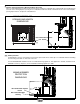
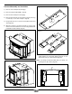
O/A Cover Screw
O/A Cover
Fig. # 5
Fig. # 6
Fig. # 7
Combustion Air
Consult local building codes regarding combustion air supply.
Intake or combustion air can be supplied to the Insert in one of
two ways:
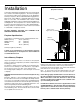
1) Outside air (O/A) supply: Remove cover from ash clean
out in existing replace. Place a rodent screen in place of
the cover. Install the Insert as described in the installation
section, making sure not to cover the opening of the air inlet.
When installation is complete, seal surround to replace and
anywhere else air may enter. This will ensure combustion air
is drawn from outside the house and into the 9” x 2” intake at
the lower rear of the appliance.
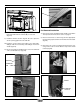
2) Room air supply: Install the Insert as described in the
installation section. When the installation is complete, do not
seal surround to replace. This will allow enough combustion
air to enter the replace cavity and the Insert. The knockouts
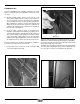
in the casing sides and the O/A cover can be removed to
supplement air supply (Fig.6 & 7). Once removed, combustion
air is drawn from the room into the lower front of the Insert.
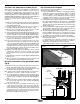
Removal: The O/A cover should be removed prior to installation.
For better access, tip the Insert onto its back.
1. Using a 5/16” wrench, remove the screw securing the O/A
cover to the rebox (Fig. #5 & 6).
This unit is not designed to be operated with the ring door open. In
addition to the obvious hazard of sparks landing on combustibles,
an open re door will cause the heater to draw air from the living
space and possibly cause suffocation.
The living space around the heater must be well ventilated with
good air circulation. Anything that may cause a negative pressure
can cause gases or fumes to be pulled into the living area.
Remove Knockout