
Operating instructions

6
ALT5.INSA 070910-24
Installation
Your Insert is designed to be installed into a masonry or factory-built,
zero-clearance wood burning replace. The masonry replace
must be built according to the requirements of the Standard of
Chimneys, Fireplaces, Vents and Solid Fuel Burning appliances,
N.F.P.A. 211 (Latest Edition) or applicable National, Provincial,
State or local codes. The installation shall conform to CAN/
CSA-B365, Installation Code for Solid-Fuel-Burning Appliances
and Equipment. The factory-built, zero-clearance replace and
its chimney must be listed per UL 127 or ULC S610 standards.
Warning: Under no circumstances is this heater to be installed
in a makeshift or "temporary" manner.
DO NOT CONNECT THIS UNIT TO A CHIMNEY FLUE
SERVICING ANOTHER APPLIANCE.
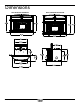
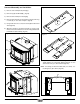
Fireplace Speci cations
Your replace is required to have the following minimum sizes:
WIDTH (at front) 24 1/2" (622 mm)
WIDTH (at rear) 24" (610 mm)
HEIGHT 21" (533 mm)
DEPTH 18 1/4" (464 mm)
Chimney height 15' (minimum)
A metal tag is provided and is to be fastened to the back
wall of the replace, if the replace has been modi ed to
accommodate the insert.
Into a Masonry Fireplace
Inspect your replace for cracks, loose mortar or other physical
defects. If repairs are required, they should be completed before
installing your insert.
The replace chimney must be suitable for wood burning use.
Check for creosote build up or other obstructions, especially if it
has not been in use for some time - have chimney swept.
The existing replace damper is to be locked open or removed
completely.
WARNING: Do not remove bricks or mortar from your existing
replace.
Exception: Masonry or steel, including the damper plate, may
be removed from the smoke shelf and adjacent damper frame if
necessary to accommodate a chimney liner, provided that their
removal will not weaken the structure of the replace and chimney,
and will not reduce protection for combustible materials to less
than that required by the National Building Code.
The Insert must be installed in accordance with local and or
national building codes. The two methods of ue connection that
are acceptable in most areas are:
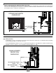
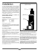
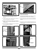
Full Flue Liner: (Fig.2) where a stainless steel rigid or exible liner
extends from the Insert ue collar to the top of the chimney.
Positive Flue Connection(In U.S.A. only): where a throat blocker
plate and a short connector pipe is used.
Note: A clean-out door may be required under local codes,
when a positive ue connection is used. Consult local codes.
Paci c Energy highly recommends the use of a full liner as
the safest installation and providing optimum performance.
When connected to a full liner, the Insert is able to draft
correctly and will prevent problems such as difficult start-
ups and smoking out the door.
For difficult installations, this insert is approved for use with
a SPND.3OFFSETA - 3” ue offset box. Only this offset box is
approved for use with this insert. The use of any other offset
box may cause a hazard and/ or void any warranty.
Rain Cap
Stainless Steel
Rigid or Flex Liner
Fig. # 2
Full Flue Liner
(Required in Canada)
Mantel or
Top Facing