
Operating instructions

12
ALT5.INSA 070910-24
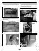
9) Reconnect the wires to the fans (Fig.29) and re-attach thermal
snap switch (Fig.30). Re t ash lip, sides and top. Ensure that
the power cable is correctly routed through the surround and
it is not touching the rebox side (Fig #31). Wire placement
is important to prevent damage to wires.
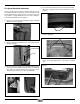
7) Remove the control assembly from the ashlip bracket on the
right hand side. Flip it over and reattach on the left hand side
of the ashlip (Fig #26). Use the upper screw holes for best
alignment.
8) Route cable from speed control to fan and reattach wire support
tabs on the underside of the ash lip. Note wire positions.
(Fig.27 & Fig.28)
WIRE SUPPORT TABS
Fig. # 26
Fig. # 27
Fig. # 28
Fig. # 31
Fig. # 29
Fig. # 30
ASHLIP BRACKETSPEED CONTROL
THERMAL
SWITCH