IMPORTANT: THESE INSTRUCTIONS ARE TO REMAIN WITH THE HOMEOWNER SAVE THESE INSTRUCTIONS By Pacific Energy Alderlea T5 Insert INSTALLATION AND OPERATING INSTRUCTIONS TESTED and LISTED to ULC S628 / UL 1482 Meets the U.S. Environmental Protection Agency's July 1990 Particulate Emission Standards 070910-24 MODEL: ALDERLEA INSERT DESIGN-D ALT5.INSA ALT5.INSA 5055.
Contents Safety ................................................................................................. 3 Clearances ......................................................................................... 3 Masonry or Factory Built Fireplace ............................................ 3 Dimensions ........................................................................................ 5 Installation ..........................................................................................
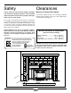
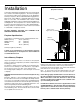
Safety Clearances Please read this entire manual before installation Masonry or Factory Built Fireplace and use of this wood burning insert. Failure to follow The minimum required clearances to surrounding combustible these instructions could result in property damage, materials when installed into a masonry or factory built fireplace bodily injury or even death. are listed below and in figure #1. We strongly recommend that smoke detectors be installed.
* Fireplace hearth requirements: (Measured without the insert) The non-combustible fireplace hearth must be raised 2” above an adjacent combustible floor and extend 16” in front and 8” beyond each side of the existing fireplace opening. A non-combustible hearth that extends a minimum 23-1/2” in front of the fireplace opening may be flush to an adjacent combustible floor.
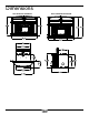
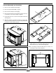
Dimensions WITH REGULAR SURROUND ALT5.
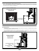
Installation Your Insert is designed to be installed into a masonry or factory-built, zero-clearance wood burning fireplace. The masonry fireplace must be built according to the requirements of the Standard of Chimneys, Fireplaces, Vents and Solid Fuel Burning appliances, N.F.P.A. 211 (Latest Edition) or applicable National, Provincial, State or local codes. The installation shall conform to CAN/ CSA-B365, Installation Code for Solid-Fuel-Burning Appliances and Equipment.
Full Flue Liner (Required in Canada) Fig #2 Into a Factory Built Fireplace This fireplace insert must be installed with a continuous liner of 6” diameter extending from the fireplace insert to the top of the chimney. The chimney liner must conform to the class 3 requirements of CAN/ULC-S635, Standard for Lining systems for Existing Masonry or Factory-Built Chimneys or Vents, or CAN/ULC-S640, Standard for lining systems for New Masonry Chimneys. In U.S.A. liner must conform to UL1777.
Combustion Air Fig. # 6 Consult local building codes regarding combustion air supply. Intake or combustion air can be supplied to the Insert in one of two ways: 1) Outside air (O/A) supply: Remove cover from ash clean out in existing fireplace. Place a rodent screen in place of the cover. Install the Insert as described in the installation section, making sure not to cover the opening of the air inlet. When installation is complete, seal surround to fireplace and anywhere else air may enter.
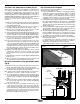
Surround Assembly and Installation Fig. # 10 1) Remove crate and all plastic packaging. 2) Remove Top(A) and Shields(B). (Fig. #8) 3) Remove Surround Top from Packaging. E 4) Remove Surround sides (C) from firebox casing by removing 2 screws (D) on each side of fireplace. (Fig #9) 5) Using a 7/16” wrench or socket, remove bolt (E) from Surround sides.(Fig #10) 6) Attach the brackets to the Surround sides as shown in Fig. #19.
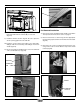
Fig. # 13 Fig. # 16 SLOT M M L L Fan Removal/Installation 8) Attach surround to firebox by aligning with bracket studs (L) then fasten with washers and nuts (M) on each side. (Fig. #13) 1) Remove Decorative Top and both Fan shields as specified in “Fan Speed Control Relocation” section on page 11. 9) Install fan shield as shown in Fig. #14. Be sure to place the air inlet opening against the surround side. 2) Disconnect fan wires as shown in Fig #17 from appropriate fan that is being replaced.
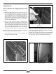
Fan Speed Controller Relocation The fan speed controller is factory installed under the ash lip on the right hand side. If required, it can be relocated to the left side by following the instructions below. To make this as easy as possible, it is suggested that this be done prior to fitting the surround and installation into the fireplace: 4) Loosen the two bolts that secure the ash lip to the firebox (Fig #23), carefully lift up the ash lip and remove from the firebox. Fig.
7) Remove the control assembly from the ashlip bracket on the right hand side. Flip it over and reattach on the left hand side of the ashlip (Fig #26). Use the upper screw holes for best alignment. Fig. # 26 SPEED CONTROL ASHLIP BRACKET 9) Reconnect the wires to the fans (Fig.29) and re-attach thermal snap switch (Fig.30). Refit ash lip, sides and top. Ensure that the power cable is correctly routed through the surround and it is not touching the firebox side (Fig #31).
Operation Wood Selection This heater is designed to burn natural wood only. Higher efficiency and lower emissions generally result when burning air-dried seasoned hardwoods, as compared to softwoods or too green or freshly cut hardwoods. Wood should be properly air dried (seasoned) for six months or more. Wet or undried wood will cause the fire to smoulder and produce large amounts of creosote. Wet wood also produces very little heat and tends to go out often.
Restarting After Extended or Overnight Burns 1) Open door and rake hot embers towards the front of the heater. Add a couple of dry, split logs on top of embers, close door. 2) Adjust air control to “H” (high) position (pushed to the far left) and in just a few minutes, logs should begin burning. 3) After wood has charred, reset air control to desired setting.
Creosote Formation and Need for Removal When wood is burned slowly, it produces tar and other organic vapours, which combine with expelled moisture to form creosote. The creosote vapours condense in the relatively cool chimney flue of a slow burning fire. As a result, creosote residue accumulates on the flue lining. When ignited, this creosote makes an extremely hot fire.
Maintenance 1. Burn wood only, dry and well seasoned. The denser or heavier the wood when dry, the greater its heat value. This is why hardwoods are generally preferred. Green or wet wood will cause a rapid buildup of creosote. If you feel it is necessary to burn wet or unseasoned wood, do so only with the air inlet set open enough to maintain a good strong fire and fairly high chimney temperatures. Do not attempt to burn overnight using green or wet wood.
Replacement Parts (WHEN ORDERING, INCLUDE PART NUMBER WITH DESCRIPTION) ITEM DESCRIPTION PART NO. 1............Regular Surround Top ...................... ALT5.SURRA ..............Oversized Surround Top .............. ALT5.SURROSA 2............Fan Shield, Left ....................................5037.47221 3............Cast Decorative Top ...............................5037.4725 4............Casing Top .......................................... SPND.4545 5............Fan Shield, Right ......................
Appendix A Understanding & Operating Your Pacific Energy Stove The Pacific Energy line of woodstoves is a culmination of years of research and development. Designed to be efficient, clean-burning and user-friendly, this heater will give you years of warm service. However, a knowledgeable operator is still the most important factor for maximum performance and part of this is understanding the basic functions of this design.
Troubleshooting Problem Cause Cure Excessive Creosote Buildup 1) Wood is too wet - Use dry wood 2) Turning down air control too soon - Do not turn down until: a) there is a good bed of coals b) the wood is charred 3) Draft too low - Improper chimney height and/or diameter - Chimney plugged or restricted, check flue - Provide outside air for combustion Glass is Dirty Low Heat Output 1) See 1, 2, and 3 above 2) Door Gasket leakage - Replace gasket - Check latch 1) Wood is wet - Use dry wood 2)
Firebrick Installation Alderlea T5 Insert This package contains 18 full-size firebricks, as well as 1 cut-size brick. With the heater in the upright position, install firebricks as follows: - Place firebricks on the bottom of the heater first. Total of 7 full-size and 1cut brick. - Next, install the side firebricks, 4 full-size each side. - Lastly, install 3 full-size firebricks against the rear wall.
NOTES: ALT5.
NOTES: 22 ALT5.
Label WN# LISTED SOLID WOOD FUEL FIREPLACE INSERT / APPAREIL DU TYPE INSERTION DE COMBUSTIBLE SOLIDE DE CHEMINÉE CERTIFIED FOR USE IN CANADA AND U.S.A./CERTIFIE AU CANADA ET AUX ETATS-UNIS TESTED TO / ÉPROUVÉ SELON: ULCS628-93 / UL1482 (2010) MODEL / MODÈLE: ALT5INS SERIES / SÉRIE: D INSTALL AND USE ONLY IN ACCORDANCE WITH PACIFIC ENERGY’S INSTALLATION AND OPERATING INSTRUCTIONS. CONTACT LOCAL BUILDING OR FIRE OFFICIALS ABOUT CODES, RESTRICTIONS AND INSTALLATION INSPECTION IN YOUR AREA.
PACIFIC ENERGY FIREPLACE PRODUCTS LTD. www.pacificenergy.net Technical Support: 1-250-748-1184 2975 Allenby Rd., Duncan, B.C. V9L 6V8 Printed in Canada 24 ALT5.