
User`s manual


Alcorn McBride Digital Video Machine DVM-7400 User’s Manual Rev 1.5
14
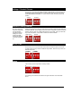
Ground Lift
In the event of AC hum, video banding, or other noise caused by potential ground
loops the first key on the 2-key DIP switch, may be opened to isolate the DVM’s ground
from its chassis. To implement a ground lift, turn this switch OFF.
Serial Port Mode
Refer to the GPS
section in this manual
for details.
When in GPS mode,
the DVM will not
respond to
Pioneer/AMI
commands.
For normal serial port control, turn ON the second key on the 4-key DIP switch. To
enable GPS mouse operation, turn this switch OFF.
Power Connector
The power input is a 2.5x5.5x10mm barrel connector with center pin (+) and the outer
rim (-). The Digital Video Machine requires 12.0 VDC to 24.0 VDC at 2 Amp. This is
useful for mobile applications where an automotive battery is used to power a
Compact Flash Card. An external 100-250 VAC 50/60Hz input universal switching
power supply is provided with the unit.
A plastic strain relief can be threaded through slots near the power input jack to
secure the barrel connector if the DVM is installed in a high-vibration environment.
DO NOT EXCEED THE SPECIFIED INPUT VOLTAGE RANGE!
Audio/Video Outputs
The audio RCA
outputs provide a
standard -10dbu
unbalanced signal.
The composite video
type can be set to
NTSC or PAL using a
DIP-switch on the
DVM’s side-panel.
Every DVM comes equipped with unbalanced stereo audio as well as composite video
outputs. These outputs are provided on RCA jacks that are color-coded.
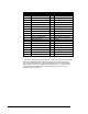
Open
Closed
Normal
GPS Mode