
User`s guide


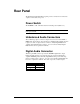


Rear Panel 13
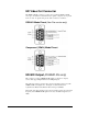
RS-232 Serial Control Port
This male DB-9 connector provides an RS-232 serial control connection. The
DVMHD will communicate using the Pioneer/AMI protocol. For information
about this using protocol, see the Pioneer / AMI Protocol section. The pinout
of this connector is as follows:
Pin Signal
1 N/C
2 RXD
3 TXD
4 N/C
5 GND
6 N/C
7 N/C
8 N/C
9 N/C
Ethernet Connector
This RJ-45 connector provides connection for a standard 100-Base TX Ethernet
cable. This cable would normally be connected to a hub, but may also be
connected directly to a PC’s Ethernet card using an Ethernet null, or “cross-
connect” cable, which is included with the DVMHD.
Ethernet is the primary mechanism for transfer of video data into the DVMHD,
and may also be used for control and monitoring. The DVMHD is shipped with
a factory default IP address of 192.168.0.254, which is useful for transferring
video across an Ethernet LAN, but must be changed if the Digital Video
Machine HD is to be connected to a router on the Internet. Refer to the
Networking Your DVMHD section of this manual for more information.
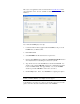
USB Connector
This connector can be used as an alternate method of loading files on the
DVMHD. Simply connect a USB storage device to the DVMHD with a
command0.bat file, and the files will be copied to the DVMHD upon start-up.
VGA Monitor Output
This connector provides the VGA output of the DVMHD. This output is helpful
for controlling the DVMHD locally as well as gathering information. Things
such as OS version, Network Information, and communication logs can be
viewed from here. To use this output, simply connect a standard PC monitor
that is able to handle an 800x600@60Hz VESA display format.