
User`s guide


Serial Control 29
Serial
Control
Serial Control
Pioneer / AMI Serial Protocol
Note: Any reference
to connectors or
serial protocols other
than Pioneer/AMI in
this section applies to
the DVM2 only.
The most versatile serial protocol of the DVM2 is the Pioneer/Alcorn McBride
Enhanced protocol. This protocol implements nearly all of the Pioneer Laser
Disc player command set, but adds commands to access advanced features of
the DVM2 such as multiple drives.
This section discusses the most commonly used commands in detail, and then
lists the entire Pioneer/Alcorn McBride Inc. protocol in tabular form.
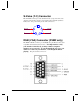
The Digital Video Machine 2 may be controlled using serial RS-232 messages
via either the DB-25 Female Sony LDP connector, the DB-15 Female Pioneer
connector, or the RS-232 wires in the 37-pin Discrete Control Connector. The
DB-15 connector allows the use of an existing Pioneer Laserdisc Player control
cable. The data format is user-defined; however, it is typically: 9600 baud, 8
bits/byte, no parity, with one stop bit. These settings are determined by the
configuration DIP switch or Web Page Setup. The protocol is ASCII-based, and
many commands are identical to Pioneer Disc protocol. Upper or lower case
characters can be used interchangeably.
Commands sent
to individual
units using the
address operator
(@) will receive
a message
response, but a
wildcard message
will not.
Addressing Commands
Any command can be preceded by <ID>@ where <ID> is the ASCII
representation of the unit’s Device ID (‘0’-‘126’). This allows
commands to be sent to individual units in a control line of multiple
units. ‘127’ and ‘*’ act as wildcard ID’ s; a command sent using ‘127’
or ‘*’ as the ID will cause all units in the control line to execute the
command. The Device ID can be assigned via the Web Page setup or
by using the Set Device ID serial command.