
User`s guide

Example Applications 97
Example
Apps
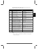
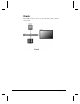
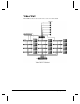
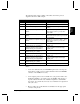
The following table contains a listing of the cables shown in the previous
diagram for the Video Wall example:
Cable From To
A-L V16+, Serial Ports 1-12 (DB9 Male) DVM2, Pioneer Port (DB15 Female)
M-R Audio Amplifier Speakers
S DVM2 #1, Sync Output (BNC) Video Distribution Amplifier, Input
(BNC)
S1 Video Distribution Amplifier, Output #1
(BNC)
DVM2 #1-4 Sync Input (BNC) – Daisy-
chain from C-Sync Loop to Sync In of
next DVM2
S2 Video Distribution Amplifier, Output #2
(BNC)
DVM2 #5-8, V16+ Sync Input (BNC) –
Daisy-chain from C-Sync Loop to Sync In
of next DVM2
S3 Video Distribution Amplifier, Output #3
(BNC)
DVM2 #9-12, Sync Input (BNC) – Daisy-
chain from C-Sync Loop to Sync In of
next DVM2
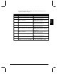
T DVM2 #5, Balanced Audio Output
(DB25 Female) pin 1(Left Main +)
Audio Amplifier, Left Channel input
(XLR), pin 2
DVM2 #5, Balanced Audio Output
(DB25 Female) pin 2 (Left Main -)
Audio Amplifier, Left Channel input
(XLR), pin 1
DVM2 #5, Balanced Audio Output
(DB25 Female) pin 3 (Shield)
U DVM2 #5, Balanced Audio Output
(DB25 Female) pin 5(Right Main +)
Audio Amplifier, Right Channel input
(XLR), pin 2
DVM2 #5, Balanced Audio Output
(DB25 Female) pin 6 (Right Main -)
Audio Amplifier, Right Channel input
(XLR), pin 1
DVM2 #5, Balanced Audio Output
(DB25 Female) pin 7 (Shield)
V1-V12 DVM2, Composite Video Output (BNC) Monitor, Video Input (BNC)
Notes:
• Some video wall cubes may use an RGBHV input instead of a Composite
input. Please consult your video wall documentation and use the RGBHV
connector on the DVM2, if necessary.
• Some designers prefer to use an external video sync generator with a video
distribution amplifier to provide the sync to the DVM2s. This involves a
separate cable run from the video distribution amplifier to each DVM2’ s
Sync input. As a general rule, it is best to use a maximum of 4 outputs from
each sync source.
• Please consult your specific hardware documentation for the appropriate
connectors and pinouts.