
Installation manual

All outputs are made using Female RJ45 connectors.
Remark:
the CPU-2 and MIX boards used for Alcatel-Lucent OmniPCX Office Compact Edition have the same
characteristics as those used by Alcatel-Lucent OmniPCX Office Communication Server.
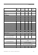
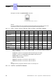
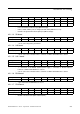
4.2.1.1.1 CPU-1, CPU-2, CPU-3, CPU-3m, CPU-4, CPUe-1 and CPUe-2 boards
RJ45 pin 1 2 3 4 5 6 7 8
LAN TX+ TX- RX+ RX-
AUDIO-OUT
Audio Out
A
Audio
Out B
Alarm A CenRg A CenRG B Alarm B Ground +12 V
CONFIG CTS DSR RX Ground Ground TX DTR RTS
MODULE1 TX+ TX- RX+ RX-
MODULE2 TX+ TX- RX+ RX-
AUDIO-IN Audio In A
Audio In
B
Audio
Ctrl A
Audio
Ctrl B
DOORPHONE
DoorPh
B1
DoorPhA1 DoorPhA2DoorPhB2
SLI1/SLI2 ZA1 ZB1 ZA2 ZB2
T01/T02 TX+ RX+ RX- TX-
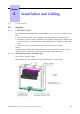
- LAN : 10/100 base T Ethernet port (MDI-II/straight), for connections between CoCPU-1,
CoCPU-2 and LAN.
- AUDIO-OUT: Interfaces Loudspeaker alarm General ringer; 12V output
- AUDIO-IN : Interfaces PLEASE WAIT MESSAGE Background music
- DOORPHONE : Interfaces doorphone
- CONFIG : RS232 for OMC.
- MODULE1: HSL link for connection to add-on module 1
- MODULE2: HSL link for connection to add-on module 2
Note:
The USB connector on the CPUe-1/CPUe-2 boards is not currently used.
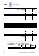
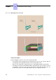
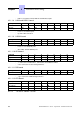
4.2.1.1.2 CoCPU-1 and CoCPU-2 boards
Chapter
4
*+
4-4