
Installation manual
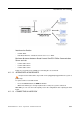
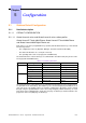


RJ45 pin 1 2 3 4 5 6 7 8
MAIN: TX+ TX- RX+ RX-
- MAIN: HSL to basic module.
4.11.1.4.3 Role of the # key
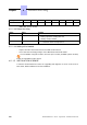
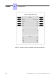
Name Color Feature
POWER Red/Green - Mains operation: steady green led
- Battery operation: steady yellow led
- Standy: steady red LED
FAN Red/Green - Both fans functioning: steady green led
- 1 or both fans down: steady red led
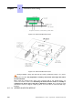
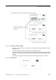
4.11.1.4.4 Adding a third module
- Replace the HSL1 board of the CPU board with an HSL2 board.
- Reuse this HSL1 board by placing it on the MEX board of the third module.
In an installation using two modules, the CPU (base module) and MEX (add on module)
boards are fitted with an HSL1 board.
4.11.1.5 INSTALLATION UPGRADE
A technical documentation describes the upgrading and migration of an R1.X, R2.X, R3.X,
R4.X, R5.X, R6.X installation to an R7.0 installation.
Chapter
4
*+
4-90