SPEED TOUCH PRO WITH FIREWALL User's Guide 3EC 36231 ABAA TCZZA Ed.
Status Change Note Released BD F aa 36170 Short Title CD-UG STPro 3.4.2 All rights reserved. Passing on and copying of this document, use and communication of its contents not permitted without written authorization from Alcatel. 2 / 288 3EC 36231 ABAA TCZZA Ed.
Contents Contents 1 Speed Touch Quick Guide . . . . . . . . . . . . . . . . . . . . . . . . . . . . . . . . . . . . . . . . . . . . 11 1.1 1.2 Get Acquainted with your Speed Touch . . . . . . . . . . . . . . . . . . . . . . . . . . . . Speed Touch Installation . . . . . . . . . . . . . . . . . . . . . . . . . . . . . . . . . . . . . . . . 1.2.1 What you Need . . . . . . . . . . . . . . . . . . . . . . . . . . . . . . . . . . . . . . 1.2.2 STPro Wiring . . . . . . . . . . . . . . . . . . . . . . . . . .
Contents 7 8 9 10 Configuration and Use - Routed Ethernet . . . . . . . . . . . . . . . . . . . . . . . . . . . . 61 7.1 7.2 7.3 Preparatory Steps . . . . . . . . . . . . . . . . . . . . . . . . . . . . . . . . . . . . . . . . . . . . . . Using Routed Ethernet . . . . . . . . . . . . . . . . . . . . . . . . . . . . . . . . . . . . . . . . . . Routed Ethernet Configuration . . . . . . . . . . . . . . . . . . . . . . . . . . . . . . . . . . . 62 63 64 Configuration and Use - Bridged PPPoE . . . . .
Contents 12.2.2 Retrieving LIS Parameters . . . . . . . . . . . . . . . . . . . . . . . . . . . . . . 12.2.3 Implicit Assignment Mechanism . . . . . . . . . . . . . . . . . . . . . . . . 12.2.4 Explicit Assignment Mechanism . . . . . . . . . . . . . . . . . . . . . . . . . 12.2.5 Configuring the STPro for CIP . . . . . . . . . . . . . . . . . . . . . . . . . . 12.2.6 Adding Appropriate Routes to the Routing Tables . . . . . . . . . . 12.2.7 Example Configuration . . . . . . . . . . . . . . . . . . . . . .
Contents 16.4 NA(P)T Configuration Example . . . . . . . . . . . . . . . . . . . . . . . . . . . . . . . . . . . 205 Network Security - Firewalling . . . . . . . . . . . . . . . . . . . . . . . . . . . . . . . . . . . . . . 207 17.1 17.2 17.3 17.4 17.5 17.6 17.7 Operation of the Firewall . . . . . . . . . . . . . . . . . . . . . . . . . . . . . . . . . . . . . . . Firewall Model . . . . . . . . . . . . . . . . . . . . . . . . . . . . . . . . . . . . . . . . . . . . . . . . Firewall Actions . . . . .
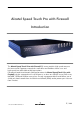
Alcatel Speed Touch Pro with Firewall Introduction The Alcatel Speed TouchPro with Firewall DSL router provides high speed access to the Internet and Corporate networks for small office and fastidious home users and high speed inter office LAN to LAN connections. For optimal Local Area Network (LAN) performance the Alcatel Speed TouchPro with Firewall includes a comprehensive set of features, as there are a DHCP server, DNS server, NAT&PAT, CIDR and VLSM to name a few.
Three STPro router variants Three variants of Alcatel's Speed TouchPro with Firewall DSL routers exist: Two Asymmetric Digital Subscriber Line (ADSL) variants: A ADSL/POTS variant connecting to an analog POTS(*) line A ADSL/ISDN variant connecting to a digital ISDN(**) line One Single pair High Speed Digital Subscriber Line (SHDSL) variant: The SHDSL variant connecting to a dedicated SHDSL two wire line.
Trademarks The following trademarks are used in this document: Speed Touch is a trademark of the Alcatel Company Netscape and Netscape Navigator are registered trademarks of Netscape Communications Corporation Windows and Internet Explorer are trademarks of Microsoft Corporation Apple and MacOS are registered trademarks of Apple Computer Inc. UNIX is a registered trademark of UNIX System Laboratories, Inc. Ethernet is a trademark of Xerox Corporation.
User's Guide updates Due to the continuous evolution of the Alcatel DSL technology, existing products are regularly upgraded. Alcatel documentation changes accordingly. For more information on the newest technological changes and documents, please consult the Alcatel web site at following Uniform Resource Locator (URL): http://www.alcatel.com http://www.alcateldsl.com 10 / 288 3EC 36231 ABAA TCZZA Ed.
1 Speed Touch Quick Guide 1 Speed Touch Quick Guide Aim of this Quick Guide In this chapter 3EC 36231 ABAA TCZZA Ed. 01 Use this chapter to quickly connect your STPro to the Internet. Topic See Get Acquainted with your STPro 1.1 STPro Installation 1.
1 Speed Touch Quick Guide 1.1 Get Acquainted with your Speed Touch Delivery check Damaged or missing items Other materials 12 / 288 Check your STPro package for the following items: The Alcatel Speed TouchPro with Firewall 1 Power supply adapter with 2m (6.56ft.) connecting cable 2m Ethernet/ATMF straight through cable (RJ45/RJ45) 2m DSL cable (RJ11/RJ11, RJ14/RJ14) This User's Guide, either in hard copy format or on CD rom.
1 Speed Touch Quick Guide The STPro The STPro is presented in a slim line box: For a detailed information and a LED description, refer to appendix B.
1 Speed Touch Quick Guide Identify your variant Use only the STPro variant which is appropriate for the DSL service delivered to your local premisses. Therefore, firstly identify your STPro via the marking label on the bottom: Q A CPYYWWNNNNN MODEL NUMBER: AA01 3EC 18704BC In the figure above, an example is provided of the marking label for a ADSL/POTS STPro variant.
1 Speed Touch Quick Guide 1.2 Speed Touch Installation Aim of this section In this section 3EC 36231 ABAA TCZZA Ed. 01 Execution of the steps in this section will bring you on the Internet in no time. Topic See What you Need 1.2.1 STPro Wiring 1.2.2 Check your SP's Service Offerings 1.2.3 Select an STPro Packet Service 1.2.4 Configure your STPro (If Necessary) 1.2.5 Surf the Internet 1.2.6 Detailed STPro Information 1.2.
1 Speed Touch Quick Guide 1.2.1 What you Need DSL service Depending on the STPro variant you purchased, the following DSL service must be available at your local premisses: ADSL service must be enabled on your telephone line. As both telephone and ADSL service are simultaneously available from the same copper pair, you need a central splitter or distributed filters for decoupling ADSL and telephone signals. SHDSL service must be enabled on a dedicated single pair copper line.
1 Speed Touch Quick Guide 1.2.2 STPro Wiring You must wire Ethernet port(s) (10Base T) The Ethernet Port(s) (10Base T) The Optional ATMF 25.6 Port (ATMF 25) The DSL Port (Line) The Power Port (DC). Use the included LAN cable to wire your PC's Ethernet port to STPro's Ethernet interface. Refer to section 2.2 for more information. Optional ATMF 25.6 port (ATMF 25) Use the included LAN cable to wire your PC's ATMF 25.6 port to the STPro's ATMF 25.6 port. Refer to section 2.
1 Speed Touch Quick Guide Check your wiring Once all connections are made the result should look similar as below: Turn on your STPro Once all previous steps are completed, turn on your STPro. The AST520 is ready for service as soon as the start up procedures are completed, the Power On Self Test (POST) is passed and both Power/Alarm and Line Sync LEDs on the front panel are constantly lit green. Refer to section B.2 for more information. 18 / 288 3EC 36231 ABAA TCZZA Ed.
1 Speed Touch Quick Guide 1.2.3 Check your Service Provider's Offering Service Offering The SP provides at least the following information: The VPI/VCI of the Virtual Channel (VC) to use on the DSL line The Connection Service supported on this VC The Encapsulation Method (if different from the Connection Service's default encapsulation). Example: VPI/VCI = 0/35 Connection Service = ETHoA (RFC1483/Br) Encapsulation Method : ETHoA default, i.e.
1 Speed Touch Quick Guide 1.2.4 Select an STPro Packet Service Connection service As soon as you know the Connection Service on a VC, you can attach a Packet Service to it.
1 Speed Touch Quick Guide 1.2.5 Configure your STPro (If Necessary) STPro access In most cases your STPro provides instant Internet connectivity as it features well chosen defaults In exceptional cases additional or advanced configurations are desired, the STPro offers various access methods: STPro configuration Its web interface (See chapter 21) A Telnet CLI session (See subsection 22.2.1) A Serial CLI session (See subsection 22.2.2). Configure the STPro via its web interface.
1 Speed Touch Quick Guide 1.2.6 Surf the Internet Finishing setup After wiring (and optionally configuring) the STPro you are ready to surf the Internet. Access methods Depending on the selected packet service(s), there is: Always on access Always On Access Dial In Access. With Transparent Bridging, Routed Ethernet and CIP & IP Routing, no connection procedure is needed. Turn on the STPro and you are online.
1 Speed Touch Quick Guide 1.2.7 Detailed STPro Information The STPro is more than just" a DSL router Use the following parts to explore STPro's advanced features: Alcatel Speed Touch Quick Guide 1 Alcatel Speed Touch Wiring Guide Ethernet and ATMF 25.
1 Speed Touch Quick Guide Alcatel Speed Touch Network Security NAT & PAT 16 Firewalling 17 Alcatel Speed Touch Maintenance Alcatel Speed Touch Software 18 Alcatel Speed Touch Password 19 Alcatel Speed Touch To Defaults 20 Alcatel Speed Touch Web Interface 21 Alcatel Speed Touch CLI 22 Alcatel Speed Touch Appendices Abbreviations 24 / 288 Alcatel Speed Touch Troubleshooting A Alcatel Speed Touch Specifications B Alcatel Speed Touch Default Assignments C Alcatel Speed Touch
Alcatel Speed Touch with Firewall Wiring Guide 3EC 36231 ABAA TCZZA Ed.
/ 288 3EC 36231 ABAA TCZZA Ed.
2 Wiring Guide - Ethernet and ATMF 25.6 2 Wiring Guide - Ethernet and ATMF 25.6 In this chapter 3EC 36231 ABAA TCZZA Ed. 01 Topic See LAN Cables 2.1 Connecting Ethernet 2.2 Connecting ATMF 25.6 (Optional) 2.3 Ethernet vs. ATMF 25.6 Connectivity 2.
2 Wiring Guide - Ethernet and ATMF 25.6 2.1 LAN Cables Included LAN cable In your STPro package, a full wired straight through RJ45/RJ45 cable, further referred to as LAN cable is included. Using LAN cables You can use LAN cables other than the one provided in the box, e.g. crossover LAN cables. However, make sure that these have the correct layout. See section B.6 for more information on how to identify straight through and crossover LAN cables.
2 Wiring Guide - Ethernet and ATMF 25.6 2.2 Connecting Ethernet In this section 3EC 36231 ABAA TCZZA Ed. 01 Topic See Ethernet Port(s) on your STPro 2.2.1 Single PC Ethernet Wiring 2.2.3 LAN Ethernet Wiring 2.2.
2 Wiring Guide - Ethernet and ATMF 25.6 2.2.1 Ethernet Port on the single Ethernet port Model Ethernet interface The Ethernet port 1 of the STPro is a 10Base T Half Duplex Ethernet interface of type MDI X: 1 Ethernet port LED The Ethernet port on the rear panel has a LED: Link Integrity LED 10Base T/MDI-X Indicator Description Name Color State Integrity Green Off No connection on this Ethernet port. On Ethernet link up. Activity No activity on this Ethernet port.
2 Wiring Guide - Ethernet and ATMF 25.6 2.2.2 Ethernet Ports on the Ethernet Hub Model Ethernet interfaces Each Ethernet port 1 of the STPro is a 10Base T Half Duplex Ethernet interface of type MDI X: 1 Ethernet port(s) LED 1 1 1 Each Ethernet port on the rear panel has a LED: Link Integrity/Activity LED 10Base T/MDI-X Indicator Description Name Color State Integrity Green Off No connection on this Ethernet port. On Ethernet link up. Activity No activity on this Ethernet port.
2 Wiring Guide - Ethernet and ATMF 25.6 2.2.3 Single PC Ethernet Wiring Single PC configuration In this configuration the STPro is connected to a single PC. Your LAN" consists of only one PC and the STPro. Procedure Proceed as indicated in the following figure to connect your STPro to a single PC: MDI 10 Base T MDI X 32 / 288 3EC 36231 ABAA TCZZA Ed.
2 Wiring Guide - Ethernet and ATMF 25.6 2.2.4 LAN Ethernet Wiring Procedure Proceed as indicated in the following figure to make the connections for a LAN (STPro hub specific connections are shaded gray): MDI MDI MDI MDI MDI MDI Hub MDI X 10 Base T MDI X Cascading Repeating Hubs CAUTION MDI vs. MDI X hub ports and the STPro You may cascade up to four repeating hubs in your LAN (limitations of Repeating Ethernet V2.0/IEEE802.3 hubs).
2 Wiring Guide - Ethernet and ATMF 25.6 2.3 Connecting the ATMF 25.6 Port (Optional) Check your STPro model ATMF 25.6 port Procedure This connection procedure applies solely to the dual port STPro model. The ATMF 25.6 port on the single Ethernet port STPro model is an ATM Forum 25.6 Mbit/s compliant interface of type ATM Network Equipment"; the PC NIC's ATMF 25.6 port is of type ATM End Equipment". Proceed as indicated in the following figure to connect the STPro ATMF 25.6 port to your PC's ATMF 25.
2 Wiring Guide - Ethernet and ATMF 25.6 2.4 Ethernet vs. ATMF 25.6 Connectivity Ethernet port(s) Due to its inherent support for networking, Ethernet will be your natural choice for creating a small LAN. ATMF 25.6 port The (optional) ATMF 25.6 port provides excellent protocol transparency and native ATM application support. Concurrent use of both ports The dual port STPro model is designed for the concurrent use of both Ethernet and ATMF 25.6 ports.
2 Wiring Guide - Ethernet and ATMF 25.6 36 / 288 3EC 36231 ABAA TCZZA Ed.
3 Wiring Guide - DSL, Power and Console 3 Wiring Guide - DSL, Power and Console In this chapter 3EC 36231 ABAA TCZZA Ed. 01 Topic See Locating Ports 3.1 Connecting the DSL Port 3.2 Connecting the Power Adapter 3.3 Connecting the Serial Port (Optional) 3.
3 Wiring Guide - DSL, Power and Console 3.1 Locating Ports Port description 4 4 5 3 5 3 Following ports are used: 38 / 288 3 : DSL line port, marked LINE" 4 : Power socket, market DC" 5 : Serial port, marked Console". 3EC 36231 ABAA TCZZA Ed.
3 Wiring Guide - DSL, Power and Console 3.2 Connecting the DSL Port ADSL vs. SHDSL In the case of: ADSL Service A central splitter, or distributed filters for decoupling ADSL and POTS or ISDN signals must be installed on your telephone line or telephone wall outlets. In some cases crossover adapters might be required. SHDSL Service As SHDSL service is delivered on dedicated wall outlets, no splitters or filters are needed. In some cases crossover adapters might be required.
3 Wiring Guide - DSL, Power and Console 3.3 Connecting the Power Adapter Introduction Power adapter types The STPro is delivered with a modular external power adapter converting the AC mains to 9VDC/1A unregulated output voltage. Check if the power adapter included in the STPro package is compatible with your local electrical power specifications. See section B.5 for connector layout and output specifications.
3 Wiring Guide - DSL, Power and Console 3.4 Connecting the Serial Port (Optional) Serial access Requirements for using the serial access Like most routers, the STPro carries a serial port on its back panel, featuring access from a remote host via a modem connection or local access from a terminal.
3 Wiring Guide - DSL, Power and Console 42 / 288 3EC 36231 ABAA TCZZA Ed.
4 Wiring Guide - Resumé 4 Wiring Guide - Resumé After wiring 3EC 36231 ABAA TCZZA Ed.
4 Wiring Guide - Resumé 44 / 288 3EC 36231 ABAA TCZZA Ed.
Alcatel Speed Touch with Firewall Configuration and Use 3EC 36231 ABAA TCZZA Ed.
/ 288 3EC 36231 ABAA TCZZA Ed.
5 Configuration and Use - Packet Services 5 Configuration and Use - Packet Services In this chapter 3EC 36231 ABAA TCZZA Ed. 01 Topic See Supported Packet Services 5.1 Packet Services at a Glance 5.2 Selection Criteria 5.
5 Configuration and Use - Packet Services 5.1 Supported Packet Services What is a packet service ? Eight packet services Packet services are the core functions of the STPro. They provide that frames or packets get forwarded from the LAN side towards the DSL line and vice versa. Transparent Bridging Routed Ethernet Bridged PPPoE Routed PPPoE Relayed PPPoA Routed PPPoA Classical IP & IP Routing ATM cell switching (*). (*) Requires the ATMF 25.6 port.
5 Configuration and Use - Packet Services 5.2 Packet Services at a Glance Access methods The STPro supports two access methods: Direct access Once initial configuration is done, continuous and immediate access is available via the DSL line. For direct access use either of: Transparent Bridging Routed Ethernet CIP & IP Routing. Dial in access In this mode access must be explicitly established, e.g. by dialing" into a Remote Access Server (RAS).
5 Configuration and Use - Packet Services Transparent Bridging Routed Ethernet The STPro IEEE802.1D Transparent Bridging packet service (further referred to as Bridging) offers complete protocol transparency and has inherent configuration simplicity. Yet it provides excellent forwarding performance. The STPro RFC1483 Routed Ethernet packet service (also referred to as MAC Encapsulated Routing (MER)) relies on standard IP Routing for its forwarding.
5 Configuration and Use - Packet Services CIP & IP Routing The STPro IP router can also be combined with Classical IP (CIP). Classical IP is a mature technique for creating classical IP networks on top of ATM technology. It is widely supported by most, if not all remote access routers. Although not the original aim of Classical IP it is mostly used for connecting routers over wide area point to point links.
5 Configuration and Use - Packet Services 5.3 Selection Criteria In this section Selection criteria Selection Criteria Simultaneous Use of Packet Services.
6 Configuration and Use - Transparent Bridging 6 Configuration and Use - Transparent Bridging Introduction See also In this chapter 3EC 36231 ABAA TCZZA Ed. 01 Transparent Bridging is the packet service of your choice as it: Is platform and OS independent Is true multiprotocol Has no performance limitations in the Alcatel implementation Has almost no constraints on the number of attached users. Routed Ethernet packet service in chapter 7. Topic See Preparatory Steps 6.
6 Configuration and Use - Transparent Bridging 6.1 Preparatory Steps Needed information VPI/VCI value of the VC(s) to use on the DSL line ETHoA (RFC1483/Bridged) connection service must be supported on these VCs Encapsulation method (LLC/SNAP) The PC's IP configuration: static or dynamic (DHCP). Note: The RFC1483 is updated by RFC2684. The STPro fully complies with the relevant sections in both RFCs. Multiple destinations You can attach up to four connections (VCs ) to the bridge.
6 Configuration and Use - Transparent Bridging 6.2 Using Bridging Bridging configuration There are no default Bridging entries. Therefore, configure an appropriate entry as follows: 1. If needed, add an ETHoA phonebook entry with the correct VPI/VCI on the 'Phonebook' page. 2. On the 'Bridge' page, select this phonebook entry from the 'Address' pop down list. 3. For this entry, select the correct encapsulation method from the 'Encapsulation' pop down list. 4. Click . See section 6.
6 Configuration and Use - Transparent Bridging 6.3 Bridging Configuration Introduction In this section The 'Bridge' page 56 / 288 This section describes the use of the STPro 'Bridge' page. The 'Bridge' Page The 'Bridging Ports' Table 'Bridging Ports' Table Components The 'Aging' Box Adding Entries Deleting Entries. Click in the left pane of the STPro pages to pop up the 'Bridging' page (See section 21.2 for more information): 3EC 36231 ABAA TCZZA Ed.
6 Configuration and Use - Transparent Bridging The 'Bridging Ports' table 'Bridging Ports' table components The following figure shows the 'Bridging Ports' table: Field Description Intf Indicates the interface name for the Bridging entry. Interface Note: In most cases, the interface name will be the same as the phonebook entry name. Address Indicates the phonebook entry used by the Bridging entry. State Indicates the state of the Bridging entry.
6 Configuration and Use - Transparent Bridging The 'Aging' box The following figure shows the 'Aging' box: It indicates the aging timer of the bridge internal database. If the aging time of a MAC entry has expired this entry will be removed from the database. Only in exceptional cases the default value of 300 seconds (5 minutes) needs to be modified. The allowed range is from 10 seconds to 12 days. Adding entries Proceed as follows: 1. Browse to the 'Bridge' page. 2. If needed, click . 3.
6 Configuration and Use - Transparent Bridging 6.4 Bridge Data Introduction The 'Bridge Data' page Available 'Bridge Data' tables 3EC 36231 ABAA TCZZA Ed. 01 Transparent Bridging completely relies on its filtering database for its frame forwarding through the bridge. This filtering database is accessible via the 'Bridge' page and allows you to overview all current MAC entries.
6 Configuration and Use - Transparent Bridging Static MAC addresses This table lists the MAC addresses you have added to the filtering database via the CLI. These MAC addresses will never be aged by the bridge. In principle, no static MAC addresses are to be configured. Permanent MAC addresses Dynamic MAC addresses These are the MAC addresses that must always be resident inside the bridge, as stipulated in the IEEE802.1D standard: The STPro's own Ethernet MAC address: e.g.
7 Configuration and Use - Routed Ethernet 7 Configuration and Use - Routed Ethernet Introduction Routed Ethernet(*) is the packet service of your choice as it: Is instantly replaceable with an IEEE Transparent Bridge Provides Always on type of connections and is auto configurable if DHCP is enabled Allows multiple users to share a single IP address if NA(P)T is enabled Allows your local network to be shielded from the Internet via STPro's programmable Firewall.
7 Configuration and Use - Routed Ethernet 7.1 Preparatory Steps Needed information Multiple destinations VPI/VCI value of the VC(s) to use on the DSL line ETHoA (RFC1483/Bridged) connection service must be supported on this VC Encapsulation method (LLC/SNAP) Whether IP configuration is static or dynamic (DHCP). The STPro can manage up to 12 Routed Ethernet connections simultaneously. Note: Check with your SP or corporate whether multiple end to end connectivity is enabled.
7 Configuration and Use - Routed Ethernet 7.2 Using Routed Ethernet Routed Ethernet configuration There are no default Routed Ethernet entries. Therefore, configure an appropriate entry as follows: 1. If needed, add an ETHoA phonebook entry with the correct VPI/VCI on the 'Phonebook' page. 2. On the 'MER' page, select this phonebook entry from the 'Address' pop down list. 3. For this entry, select the correct encapsulation method from the 'Encapsulation' pop down list. 4. DHCP is per default on ( ).
7 Configuration and Use - Routed Ethernet 7.3 Routed Ethernet Configuration Introduction In this section The 'MER' page 64 / 288 This section describes the use of the STPro 'MER' page. The 'MER' Page The 'MER Settings' Table 'MER Settings' Table Components Adding Entries Deleting Entries. Click in the left pane of the STPro pages to pop up the 'MER' page (See section 21.2 for more information): 3EC 36231 ABAA TCZZA Ed.
7 Configuration and Use - Routed Ethernet The 'MER Settings' table 'MER Settings' table components The following figure shows the 'MER Settings' table: Field Description Intf Indicates the interface name for the Routed Ethernet entry. Interface Note: In most cases, the interface name will be the same as the phonebook entry name. Address Indicates the phonebook entry used by the Routed Ethernet entry. State Indicates the state of the Routed Ethernet interface.
7 Configuration and Use - Routed Ethernet Field Description MAC Address Indicates the MAC address for the Routed Ethernet entry. Note: In case no MAC address is entered manually, the source MAC address of the Ethernet frames is the STPro Ethernet MAC address. NAT Indicates whether NA(P)T is used ( ) or not on the IP address of the Routed Ethernet entry. DHCP Indicates whether DHCP is used ( ) or not for the Routed Ethernet entry.
8 Configuration and Use - Bridged PPPoE 8 Configuration and Use - Bridged PPPoE Introduction The STPro transparent bridge can be used in combination with a PPP over Ethernet (PPPoE) client installed on your PC. The resulting Bridged PPPoE packet service provides similar dial in experience as found on point to point connections. See also In this chapter 3EC 36231 ABAA TCZZA Ed. 01 Routed PPPoE packet service in chapter 9. Topic See Preparatory Steps 8.1 Using Bridged PPPoE 8.
8 Configuration and Use - Bridged PPPoE 8.1 Preparatory Steps Needed information Multiple destinations VPI/VCI value of the VC(s) to use on the DSL line ETHoA (RFC1483/Bridged) connection service must be supported on this VC Encapsulation method (LLC/SNAP) Remote access server must be a PPPoE server PPPoE client to be installed User name and password for your user account. Up to four simultaneous Bridged PPPoE sessions can be active.
8 Configuration and Use - Bridged PPPoE 8.2 Using Bridged PPPoE Creating and using a PPPoE session instance Via the PPPoE client, you will be able to create PPPoE session icons, representing all the connection parameters, just like creating Dial Up icons with Microsoft's Dial Up Networking application. All you need is your username and password for your account; although sometimes also a Service Name and/or Access Concentrator is required.
8 Configuration and Use - Bridged PPPoE 8.3 Bridged PPPoE Configuration Introduction As the Bridged PPPoE packet service implies nothing more than using the STPro Transparent Bridging packet service, no specific configuration for Bridged PPPoE is required on the STPro. However, you may need to configure the Transparent Bridging packet service of the STPro in order to meet the requirements of your SP regarding VC(s) and encapsulation. Bridging configuration There are no default Bridging entries.
9 Configuration and Use - Routed PPPoE 9 Configuration and Use - Routed PPPoE Introduction Routed PPPoE(*) is the packet service of your choice as it: Provides the dial in access method over a virtual Ethernet segment Requires no PPPoE client on the PC(s), avoiding special installation procedures Allows multiple users to share a single IP address if NA(P)T is enabled Allows your local network to be shielded from the Internet via STPro's programmable Firewall.
9 Configuration and Use - Routed PPPoE 9.1 Preparatory Steps Needed information Multiple destinations VPI/VCI value of the VC(s) to use on the DSL line ETHoA (RFC1483/Bridged) connection service must be supported on this VC Encapsulation method (LLC/SNAP) Remote access server must be a PPPoE server Username and password for your user account. The STPro can manage up to 12 Routed PPPoE connections simultaneously.
9 Configuration and Use - Routed PPPoE 9.2 Using Routed PPPoE Routed PPPoE configuration There are no default Routed PPPoE entries. Therefore, configure the appropriate as follows: 1. If needed, add an ETHoA phonebook entry with the correct VPI/VCI on the 'Phonebook' page. 2. On the 'PPP' page, select this phonebook entry from the 'Address' pop down list. 3. For this entry, select PPPoE in the 'Protocol' field. 4. Select the correct encapsulation method from the 'Encapsulation' pop down list. 5.
9 Configuration and Use - Routed PPPoE 5. If applicable an 'Authentication' table pops up: Enter your username and password in the appropriate fields. If you want the STPro to remember your credentials, check 'Save password' ( ). 6. Click . 7. After identification and authentication the 'PPP connections' page reappears. While the STPro tries to open the session 'trying' will appear in the 'State' field. Once the session is active the field displays 'up'.
9 Configuration and Use - Routed PPPoE 9.3 Routed PPPoE Configuration Introduction This section describes the use of the STPro 'PPP' page for Routed PPPoE. Note Most, if not all configurations for Routed PPPoE connections are identical to the configuration of Routed PPPoA connections. Therefore most configurational aspects in this section will be referred to the configuration sections of chapter 11.
9 Configuration and Use - Routed PPPoE Adding entries Proceed as follows: 1. Browse to the 'PPP' page. 2. If needed, click . 3. Select the PPPoE protocol from the 'Protocol' pop down list. 4. Select the phonebook entry from the 'Address' pop down list. You must use a ETHoA or any type" phonebook entry for Routed PPPoE connections. Note: In case the presented phonebook entries do not suite your desired configuration, you must firstly create a correct phonebook entry. See section 13.
9 Configuration and Use - Routed PPPoE 9.4 Detailed Configuration Introduction Additional configuration of the Routed PPPoE entry may be needed in the 'Detailed Configuration' table. This section describes the various PPPoE connection configurations the STPro offers for assuring end to end connectivity. The 'Detailed Configuration' table On the 'PPP' page a 'Detailed Configuration' table can be found.
9 Configuration and Use - Routed PPPoE 9.4.1 'PPPoE' Configurations The 'PPPoE' tab PPPoE Service and Access Concentrator 78 / 288 The STPro Routed PPPoE embedded session client allows to configure your PPPoE session for connecting for a dedicated Service via an Access Concentrator. If applicable, both Service name and Access Concentrator will be provided by the SP. For more information, contact your SP. 3EC 36231 ABAA TCZZA Ed.
9 Configuration and Use - Routed PPPoE 9.4.2 'Routing' Configurations The 'Routing' tab Configurable items The 'Routing' tab allows you to configure the IP routing aspects of the selected Routed PPPoE entry. Following routing aspects are configurable: Connection sharing This field allows you to configure which LAN members, besides the PC that opened the Routed PPPoE session, can use the connection.
9 Configuration and Use - Routed PPPoE 9.4.3 'Other' Configurations The 'Other' tab Configurable items The 'Other' tab allows you to configure the connection related aspects of the selected Routed PPPoE entry. Following connection aspects are configurable: Mode This field allows you to configure how the Routed PPPoE session is opened. Idle time limit For 'Dial on demand' this checkbox allows you to specify the time after which a running but unused PPPoE session is closed.
9 Configuration and Use - Routed PPPoE 9.4.4 'Stats' During a Routed PPPoE Session The 'Stats' tab Configurable items During a Routed PPPoE session a fourth tab 'Stats' is available: The 'Stats' tab allows to overview some session statistics while a session is running on the selected Routed PPPoE entry. Following session statistics are available: IP Address The IP address at the local peer of the current PPP link.
9 Configuration and Use - Routed PPPoE 82 / 288 3EC 36231 ABAA TCZZA Ed.
10 Configuration and Use - Relayed PPPoA 10 Configuration and Use - Relayed PPPoA Introduction Relayed PPPoA(*) is the packet service of your choice as it: Provides standard Dial in PPP behavior Supports security via identification, authentication and encryption Has multiprotocol support depending on the PPTP implementation, e.g.
10 Configuration and Use - Relayed PPPoA 10.1 Preparatory Steps Needed information Multiple destination VPI/VCI value of the VC(s) to use on the DSL line PPPoA (RFC2364) connection service must be supported on this VC Encapsulation method (VC MUX) Remote access server must be a PPP(oA) server Username and password for your user account. The STPro can manage up to 12 Relayed PPPoA connections simultaneously.
10 Configuration and Use - Relayed PPPoA 10.2 Using Relayed PPPoA Introduction Before you can open a PPTP tunnel towards the STPro, firstly you must initially configure a PPTP dial up connection on your PC. Once this PPTP dial up connection is configured you can use it to open a Relayed PPPoA connection to the remote side of the DSL line. Because the configuration and use of such a connection follows similar patterns for all popular OSs, this section will describe the procedures in global. In section 10.
10 Configuration and Use - Relayed PPPoA 10.2.1 Preparing the PC for PPTP Tunneling Creating a PPTP connection icon Most, if not all OSs provide a Graphical User Interface (GUI) guided procedure for the initial creation of a PPTP connection icon. The result of such creation is in most cases an icon, or entry in a folder or a table called 'RAS', 'Dial Up Networking', 'PPTP', 'Call sessions', etc.
10 Configuration and Use - Relayed PPPoA 10.2.2 Using PPTP towards your STPro PPPoA configuration Per default, following PPPoA phonebook entries are available for Relayed PPPoA connections: RELAY_PPP1 (PPPoA on 8.48) RELAY_PPP2 (PPPoA on 8.49) RELAY_PPP3 (PPPoA on 8.50) RELAY_PPP4 (PPPoA on 8.51) DIALUP_PPP3 (PPPoA on 8.66) In case these PPPoA phonebook entries do not meet your requirements, you can configure a new one. See section 13.3 for more information.
10 Configuration and Use - Relayed PPPoA 10.3 Example : MS Windows 98 Dial Up Networking In this section The following overview summarizes the necessary steps to setup a Microsoft Windows 98 PC for the use of Relayed PPPoA: Step 88 / 288 Action See 1 Configure a Private IP address on your PC 2 Create a new Dial Up Networking icon 10.3.1 5 Open a Dial Up Session 10.3.2 6 Surf the Internet. 7 Close a Dial Up Session in Use 10.3.3 3EC 36231 ABAA TCZZA Ed.
10 Configuration and Use - Relayed PPPoA 10.3.1 Create a New Dial Up Networking Icon Procedure Proceed as follows: Step Action and Description 1 Double click the 'My Computer' icon on your desktop. 2 Double click the 'Dial Up Networking' icon. 3 Double click the 'Make New Connection' icon to activate the 'Make New Connection' wizard. 4 If you use the Dial Up Networking application for the first time, the 'Welcome to Dial Up Networking' window appears.
10 Configuration and Use - Relayed PPPoA Step 5 Action and Description In the first input field of the 'Make New Connection' window, type a name, e.g. an alias for the organization you are connecting to. Note: This name will appear below the Dial Up icon at the end of this procedure. 6 In the 'Select a device' pop down list of the 'Make New Connection' window, you must select the 'Microsoft VPN Adapter' for PPTP tunneling.
10 Configuration and Use - Relayed PPPoA Result A new icon with the name of the connection you have just created will be added to your 'Dial Up Networking' folder: Creating multiple Dial Up icons for multiple destinations Per destination you can create a unique icon. To do so, repeat the steps starting with step 3 of the previous procedure. 3EC 36231 ABAA TCZZA Ed.
10 Configuration and Use - Relayed PPPoA 10.3.2 Open a Dial Up Session Procedure Proceed as follows: Step 1 Action and Description Double click the appropriate Dial Up icon in the 'Dial Up Networking' folder or double click its shortcut on your desktop. The 'Connect To' window pops up: 2 Fill in your user name and password, according your user account at the SP or Corporate.
10 Configuration and Use - Relayed PPPoA While you are connected Once the Dial Up connection is established, you can find the MSDUN icon showing two PCs connected to each other in the system tray: The MSDUN icon symbolizes activity on the Relayed PPPoA connection by flashing PC(s): The 'Connected To' window A flashing Front" PC symbolizes upstream (TX) link activity (from your local PC towards the STPro) A flashing Behind" PC symbolizes downstream (RX) link activity (from the STPro towards you
10 Configuration and Use - Relayed PPPoA 10.3.3 Close a Dial Up Session in Use Procedure Proceed as follows: Step 1 Action and Description If the Dial Up connection is minimized, click the MSDUN icon the system tray: in The 'Connected To' window pops up: 2 Result 94 / 288 Click to close the session. The PPTP tunnel to the STPro will no longer exist. The Relayed PPPoA entry on the STPro is made available again for other users. 3EC 36231 ABAA TCZZA Ed.
10 Configuration and Use - Relayed PPPoA 10.4 Relayed PPPoA Configuration Introduction In this section The 'PPTP' page 3EC 36231 ABAA TCZZA Ed. 01 This section describes the use of the STPro 'PPTP' page. The 'PPTP' Page The 'Active PPTP Connections' Table 'Active PPTP Connections' Table Components Advanced Configuration Tunneling from behind an IP Router. Click in the left pane of the STPro pages to pop up the 'PPTP' page (See section 21.
10 Configuration and Use - Relayed PPPoA The 'Active PPTP Connections' table The following figure shows the 'Active PPTP Connections' table: In the example one active Relayed PPPoA connection is up. 'Active PPTP Connections' table components Field Description Dial string In your Dial Up application you are able to specify which PPPoA entry (and PPTP profile) is to be used by adding the appropriate dial string. This dial string is indicated here, if applied.
10 Configuration and Use - Relayed PPPoA Field Description HDLC In order to cope with these PPP frame differences, the STPro adapts to the different formats on a 'per connection' base.
10 Configuration and Use - Relayed PPPoA Tunneling from behind an IP router The STPro allows local tunneling from behind an IP router: 172.16.0.2 IP Router Local PPTP tunnels 172.16.0.1 10.0.0.138 Ethernet LAN 10.0.0.1 IP Network 10 IP Network 172.16 172.16.0.3 This requires settings in both STPro and PCs. STPro You must add a default route for the STPro via the 'Routing' page (See section 14.5 for more information).
11 Configuration and Use - Routed PPPoA 11 Configuration and Use - Routed PPPoA Introduction Routed PPPoA(*) is the packet service of your choice as it: Has an authenticated session concept: it supports identification, authentication and autoconfiguration Requires no session client on the PC(s), avoiding special installation procedures Allows multiple users to share a single IP address if NA(P)T is enabled Allows your local network to be shielded from the Internet via STPro's programmable F
11 Configuration and Use - Routed PPPoA 11.1 Preparatory Steps Needed information Multiple destinations VPI/VCI value of the VC(s) to use on the DSL line PPPoA (RFC2364) connection service must be supported on this VC Encapsulation method (VC MUX) Remote access server must be a PPP(oA) server Username and password for your user account. The STPro can manage up to 12 Routed PPPoA connections simultaneously.
11 Configuration and Use - Routed PPPoA 11.2 Using Routed PPPoA Access methods for PPP Three methods exist to open a Routed PPPoA session: Dial in The session is opened manually Always on After the STPro is powered and finished its POST successfully, the STPro automatically tries to open the session Dial on demand The session is opened automatically, triggered by the arrival of packets at a/the STPro Ethernet port, destined for a Routed PPPoA connection.
11 Configuration and Use - Routed PPPoA Opening dial in sessions Proceed as follows (See section 21.2 for more information): 1. Click on the STPro pages. 2. On the 'Dial in' page the following table is shown: 3. Click next to the PPPoA entry you want to connect with. As a result your selection is highlighted. 4. Click . 5. If applicable an 'Authentication' table pops up: Enter your username and password in the appropriate fields.
11 Configuration and Use - Routed PPPoA During the session During the time the session is up, you can overview some important connection statistics on the 'PPP' page. See section 11.4.3 for more information. Closing dial in PPPoA sessions Proceed as follows: 1. Browse to the 'Dial in' page. 2. Active PPPoA sessions are indicated via up in the 'State' field. Click next to the active PPPoA entry in the list you want to close the session for. As a result your selection is highlighted. 3. Click .
11 Configuration and Use - Routed PPPoA 11.3 Routed PPPoA Configuration Introduction This section describes the use of the 'PPP' page for Routed PPPoA and Routed PPPoE connectivity. Prior to be able to use a Routed PPPoA or Routed PPPoE entry you may need to configure it. This is described in section 11.4. For more information on the use of the Routed PPPoE packet service of the STPro see chapter 9.
11 Configuration and Use - Routed PPPoA The 'PPP configuration' table 'PPP Configuration' table components The following figure shows the 'PPP Configuration' table: Field Description Interface Indicates the interface name for the PPP entry. Note: In most cases, the interface name will be the same as the phonebook entry name. Destination Indicates available phonebook entries for Routed PPPoA and Routed PPPoE.
11 Configuration and Use - Routed PPPoA Field Description Link Indicates the link state of the PPP entry. It can take following values: Value idle Description The PPP entry is not activated, i.e. it does not setup a PPP connection. Connected The PPP entry is active, i.e. it tries to setup a PPP connection, or PPP connectivity is achieved. State Indicates the active state of the PPP session. It can take following values: Protocol Value Up Description The PPP session is opened and active.
11 Configuration and Use - Routed PPPoA Adding entries Proceed as follows: 1. Browse to the 'PPP' page. 2. If needed, click . 3. Select the PPPoA protocol from the 'Protocol' pop down list. 4. Select the phonebook entry from the 'Address' pop down list. Free PPPoA and ETHoA phonebook entries are shown as well as free any" type phonebook entries. You must use a PPPoA or any" type phonebook entry for Routed PPPoA.
11 Configuration and Use - Routed PPPoA 11.4 Detailed Configuration Introduction Additional configuration of the Routed PPPoA connection may be needed in the 'Detailed Configuration' table. This section describes the various PPPoA connection configurations the STPro offers for assuring end to end connectivity. The 'Detailed Configuration' page On the 'PPP' page a 'Detailed Configuration' table can be found.
11 Configuration and Use - Routed PPPoA 11.4.1 'Routing' Configurations Introduction Advanced routing If a PPP session is opened successfully (either manually by the user, triggered by LAN traffic or automatic at boot time) routes are automatically added to the STPro's routing table. The settings in the PPP 'IP Routing' box, are reflected in the routing table. For advanced users, the STPro allows manual configuration of permanent routes to dedicated destinations. See section 14.
11 Configuration and Use - Routed PPPoA Connection sharing The 'Connection Sharing' field allows you to configure which LAN members, besides the PC that opened the PPP session, can use the PPP entry. Three options are available: Only Me Only frames of the PC that opened the PPP session will be routed via this PPP entry. Suppose you opened a PPP session to your corporate and other LAN members are surfing the Internet.
11 Configuration and Use - Routed PPPoA 'My net only' configuration In case you want to privilege access via a particular PPP entry for specific PCs, proceed as follows: Step 1 Action Configure the PCs, to which you want to privilege outbound access via this PPP entry, in a particular subnet of your local LAN. Note: Do not forget to make the STPro also a member of this workgroup. 2 Configure the 'Connection Sharing' box of the particular PPP entry for 'My net only'.
11 Configuration and Use - Routed PPPoA Destination networks subnet values 112 / 288 The following table lists the default used classful netmasks related to the four possible options: Connection Sharing value Related Source Subnet Mask Notation All networks 0.0.0.0 /0 Remote net only 255.255.255.0 /0 Remote host only 255.255.255.255 /32 Specific network 255.255.255.0.0 (default) /* defined below This value is depending on the destination subnet mask. 3EC 36231 ABAA TCZZA Ed.
11 Configuration and Use - Routed PPPoA 11.4.2 'Other' Configurations Introduction In this subsection 'Other' tab 3EC 36231 ABAA TCZZA Ed. 01 The following paragraphs explain which options that are used by a PPP entry when it opens a PPP session. 'Other' Tab Mode: Triggering of a PPP Session Idle Time Limit Local and/or Remote IP: STPro PPP Client/Server Behavior Primary and Secondary DNS Server LCP Echo ( ) Requests PAP ( ): Authentication Protocols.
11 Configuration and Use - Routed PPPoA Mode: triggering of PPP session The 'Mode' field allows you to configure how a PPP session is opened. Three options are available: Dial in The PPP session is opened manually by clicking to the PPP connection in the 'Dial in' page. next Always on After the STPro is powered and finished its Power On Self Test (POST) successfully, the STPro automatically tries to open a PPP session for the PPP entry.
11 Configuration and Use - Routed PPPoA Local and/or remote IP: STPro PPP server/client behavior During the opening of a PPP session, IP addresses are negotiated between the two PPP peers for the PPP entry. The 'Local IP' and 'Remote IP' fields influence this negotiation. Typically at the client side, the 'Local IP' and 'Remote IP' fields are left empty. This forces the client to ask the RAS for IP addresses.
11 Configuration and Use - Routed PPPoA PAP ( ): used authentication protocol The STPro features two authentication protocols to be used: Challenge Handshake Authentication Protocol (CHAP) Password Authentication Protocol (PAP). Per default the STPro will negotiate CHAP with the BroadBand RAS (BBRAS) as it is the safest authentication protocol. However, PAP will be allowed, if needed. Checking the PAP flag ( ) will force the STPro only to negotiate PAP with the BBRAS.
11 Configuration and Use - Routed PPPoA 11.4.3 'Stats' During a Routed PPPoA Session The 'Stats' tab During a Routed PPPoA session a fourth tab 'Stats' is available: Configurable items The 'Stats' tab allows to overview some session statistics while a session is running on the selected Routed PPPoA entry. Following session statistics are available: IP Address The IP address at the local peer of the current PPP link.
11 Configuration and Use - Routed PPPoA 118 / 288 3EC 36231 ABAA TCZZA Ed.
12 Configuration and Use - CIP & IP Routing 12 Configuration and Use - CIP & IP Routing Introduction Classical IP & IP routing(*) is the packet service of your choice as it: Is a third standardized method next to PPPoA and PPPoE for creating IP networks on top of ATM technology Is traditionally well supported by ATM access routers at the remote end of the connection Similar to Bridging, provides "Always on" type of connections.
12 Configuration and Use - CIP & IP Routing 12.1 Preparatory Steps Needed information VPI/VCI value of the VC(s) to use on the DSL line IPoA (RFC1483/Routed) connection service must be supported on this VC Encapsulation method (LLC/SNAP) For full compliancy to RFC1577 the remote access device must issue and respond to InATMARP messages. Note: The RFC1577 on which Classical IP over ATM relies is updated by RFC2225. The STPro fully complies with both RFCs.
12 Configuration and Use - CIP & IP Routing 12.2 CIP Configuration for a LIS Introduction In this section 3EC 36231 ABAA TCZZA Ed. 01 This section describes the basic procedures to enable connectivity in a Logical IP Subnet (LIS) via the ATM core network. Topic See General CIP Configuration Procedure 12.2.1 Retrieving LIS Parameters 12.2.2 Implicit Assignment Mechanism 12.2.3 Explicit Assignment Mechanism 12.2.4 Configuring the STPro for CIP 12.2.
12 Configuration and Use - CIP & IP Routing 12.2.
12 Configuration and Use - CIP & IP Routing 12.2.2 Retrieving LIS Parameters LIS The LIS is an important CIP concept. It is a group of IP machines configured as members of the same IP subnet. In other words: they share the same IP network and subnetwork numbers. In most cases this LIS will be a corporate LAN/WAN environment, which is interconnected via the DSL/ATM network.
12 Configuration and Use - CIP & IP Routing 12.2.3 Implicit Assignment Mechanism Implicit assignment If the remote side is RFC1577/RFC2225 compliant, e.g. another STPro, your local STPro is able to retrieve the remote IP address of the CIP PVC, by issuing an InATMARP request on that PVC. That way, you must not specify an IP address for the CIP PVCs you add to the 'CIP Connections' table, it will be implicitly assigned when connecting to the LIS.
12 Configuration and Use - CIP & IP Routing 12.2.4 Explicit Assignment Mechanism Explicit assignment In the case of a remote access server which is not RFC1577/RFC2225 compliant, it will not respond to InATMARP requests. As a consequence, the STPro can not retrieve the remote IP address to assign the CIP PVC to the CIP member. Therefore you must explicit assign a remote IP address to the CIP PVC.
12 Configuration and Use - CIP & IP Routing 12.2.5 Configuring the STPro for CIP Introduction After retrieving the LIS parameters, you must configure the STPro, according to these parameters. This section describes in short the global procedure for configuring your STPro 'Phonebook' and 'CIP' pages. Configuration of the STPro 'Phonebook' page By default the STPro is configured for a CIP VC as used in the example of section 12.2.7.
12 Configuration and Use - CIP & IP Routing 12.2.6 Adding Appropriate Routes to the Routing Tables Introduction to routing IP routing is a very important aspect for a LIS configuration. This subsection describes how you can ensure end to end connectivity for a CIP environment.
12 Configuration and Use - CIP & IP Routing Configuring the STPro for LIS connectivity, advanced The possibility exists to add routes yourself, e.g. to be more specific in the source IP address pool. The default added routes have any as source address, meaning that all local hosts can use this gateway to connect to the LIS via the CIP interface. However, you might want to embed restrictions in LIS access by creating a subnet in your LAN, e.g. 10.0.1.
12 Configuration and Use - CIP & IP Routing 12.2.7 Example Configuration Configuration figure The configuration of a Classical IP LIS is illustrated with the following example: Subnet 10.1 8/80 LIS 172.16.1.x ETH 8/80 2 192.168.0.1 255.0.0.0 1 172.16.1.2 255.255.255.0 10.0.0.0->172.16.1.1 Local Servers 10.0.0.1 255.0.0.0 10.0.0.138<-0.0.0.0 ATM ETH ATM 192.168.0.2 255.255.255.0 0.0.0.0.->192.168.0.1 172.16.1.1 255.255.255.0 10.0.0.138 255.0.0.0 172.16.1.2<-0.0.0.
12 Configuration and Use - CIP & IP Routing Remote premisses configuration Routing configuration At the remote DSL side, the CIP LIS is terminated by access router(2) and IP packets are forwarded to local servers or the Internet and vice versa. Here, the CIP member is configured with IP address 172.16.1.2 and is part of the same LIS 172.16.1.x. Additionally, a VC with the same VPI/VCI values 8/80 is assigned to this CIP member (e.g. implicit assignment, because STPro(1) is RFC1577/RFC2225 compliant).
12 Configuration and Use - CIP & IP Routing 12.3 Using CIP & IP Routing CIP operation Similar to classical LAN networking CIP & IP Routing adheres to the "always on" concept. IP packets sourced by local PCs, arrive via the Ethernet segment in the STPro. The latter makes routing decisions based on the destination IP address of the packet. If the packet ends up in the CIP member it will on its turn determine to which VC it has to output the packet.
12 Configuration and Use - CIP & IP Routing 12.4 CIP Configuration Introduction In this section The 'CIP' page 132 / 288 This section describes the use of the STPro 'CIP' page. The 'CIP' Page The 'CIP Interfaces' Table 'CIP Interfaces' Table Components The 'CIP connections' Table 'CIP Connections' Table Components Adding CIP members Assigning CIP PVCs to CIP members Deleting CIP Entries.
12 Configuration and Use - CIP & IP Routing The 'CIP Interfaces' table 'CIP Interfaces' table components The following figure shows the 'CIP Interfaces' table: Field Description Intf Indicates the CIP member name. All CIP members are named 'cipX', where X is a number. Local Address Indicates the IP address of the local DSL side of the LIS, i.e. the IP address of your CIP interface. Mask Indicates the netmask/subnetmask of the local IP address. Note: The netmask may be classful or classless.
12 Configuration and Use - CIP & IP Routing The 'CIP Connections' table 'CIP Connections' table components The following figure shows the 'CIP Connections' table: Field Description Dest Indicates the CIP VC phonebook name. Remote Address Indicates the remote IP address of the remote DSL side of the LIS, i.e. the IP address of the remote CIP interface. Note: In case the VC is not cross connected, or implicit assignment was not successful, this field shows Unresolved".
12 Configuration and Use - CIP & IP Routing Adding CIP members Proceed as follows: 1. Browse to the 'CIP' page. Addition of a CIP member is performed in the 'CIP Interfaces' table. 2. If needed, click in the 'CIP Interfaces' table. 3. Enter in the following CIP member parameters: Local IP address The IP address of the CIP member at your local side of the LIS. Mask The associated classful or classless netmask/subnetmask for this local IP address. 4. Click Result and to finish the procedure.
12 Configuration and Use - CIP & IP Routing Assigning CIP PVCs to CIP members Proceed as follows: 1. Browse to the 'CIP' page. Assignment of a CIP PVC is performed in the 'CIP Connections' table. 2. If needed, click in the 'CIP Connections' table. 3. Select the phonebook entry from the 'Destination' pop down list. You must use a IPoA or any type" phonebook entry for CIP connections.
Alcatel Speed Touch with Firewall Networking 3EC 36231 ABAA TCZZA Ed.
/ 288 3EC 36231 ABAA TCZZA Ed.
13 Networking - ATM 13 Networking - ATM Introduction All data arriving at and departing from your STPro via the DSL line is carried in Asynchronous Transfer Mode (ATM) cells. In this way, ATM is the fundamental communication language" for the STPro towards the remote devices. The dual port STPro model, equipped with the additional ATMF 25.6 port, is even capable to extend ATM connectivity up to your local PC or local network (via ATM switches). In this chapter 3EC 36231 ABAA TCZZA Ed.
13 Networking - ATM 13.1 The ATM Packet Switching Technology ATM Switching ATM is a connection oriented packet switching technology using fixed size packets, called cells. These cells consist of a header and a payload and are switched through a public or private ATM network depending on the contents of the header. End to end connections are formed by cross connecting individual ATM segments in ATM switches. In this section 140 / 288 Topic See ATM Parameters 13.1.1 ATM and the STPro 13.1.
13 Networking - ATM 13.1.1 ATM Parameters Virtual channels ATM uses VCs to create individual communication links between network nodes. ATM uses two types of VCs: Permanent Virtual Channels (PVCs) are static connections between network nodes that are configured statically. For a Permanent Virtual Channel (PVC) the nodes of the connection operate as if they are connected with a dedicated physical line. Switched Virtual Channels (SVCs) are similar to voice telephone network connections.
13 Networking - ATM 13.1.2 ATM and the STPro End to end ATM connectivity The following figure provides an overview of the end to end architecture of the ATM connectivity; from your STPro to remote access devices. Internet ISP Access Point ATM Cross connect Multiple ATM virtual channels Corporate Access Point Remote LAN ATM Cross connect DSL Line Ethernet ATMF 25.6 This channel is not cross connected Hence no end to end connectivity! Symbolizes a cross connection. STPro vs.
13 Networking - ATM 13.1.3 ATM and Interfaces ATM traffic handling ATM traffic arriving at the STPro is switched to either the Ethernet port(s) or the (optional) ATMF 25.6 port depending on the VPI/VCI values in the individual cells. Inside ATM VCs any protocol can be transported. However, at both endpoints - that is where the ATM channels are terminated - the same protocol must be supported. If not, there will be no end to end connectivity.
13 Networking - ATM Ethernet port(s) This port terminates a number of ATM connections and extracts frames from arriving cells and encapsulates frames in departing cells. Only frames recognized/supported by the STPro on a particular ATM connection are extracted, or encapsulated. Currently the supported encapsulations are: For Transparently Bridged connections: RFC 1483, Ethernet V2.0/IEEE 802.
13 Networking - ATM 13.2 ATMF 25.6 Port Configuration Disclaimer ATM connectivity in your LAN This section applies only to the dual port STPro model, equipped with both Ethernet and ATMF 25.6 port. If your PC (alternatively via an ATM switch) is connected to the ATMF 25.6 port, ATM service is delivered into the PC. This implies that ATM cells, sourced by PC applications via the PC's ATMF PC NIC port are captured by the STPro ATMF 25.6 port and cross connected or switched to the DSL line.
13 Networking - ATM 13.3 The Speed Touch Phonebook Introduction The STPro phonebook is like any ordinary phonebook: A repository for names and numbers". However, in contrast to a standard phonebook it contains additional connectivity information. Basic to the STPro operation are ATM VCs. The STPro phonebook is the management tool for all possible ATM connections. This chapter describes how to use the STPro phonebook and consequently how to manage this VC pool.
13 Networking - ATM 13.3.1 The STPro 'Phonebook' Page In this subsection The 'Phonebook' page 3EC 36231 ABAA TCZZA Ed. 01 The 'Phonebook' Page The 'Phonebook' Table 'Phonebook' Table Components Phonebook Defaults The 'ATMF ADSL Xconnects' Table The 'AutoPVC' Table. Click in the left pane of the STPro pages to pop up the 'Phonebook' page (See section 21.
13 Networking - ATM The 'Phonebook' table 'Phonebook' table components The following figure shows an example of the 'Phonebook' table of the 'Phonebook' page: Field Description Name Indicates the name, or alias of the phonebook entry. Any name can be given to an entry. Address Indicates the VPI and VCI value of the ATM VC terminated on the DSL port for the phonebook entry. The allowed VPI range: from 0 up to 15. The allowed VCI range: from 32 up to 511.
13 Networking - ATM Field Description Type Represents the connection service supported on the ATM VC. It can take the following values: Value ETHoA Packet Service Transparent Bridging RFC1483/Br See chapter 6 for more information. Routed Ethernet (MER) See chapter 7 for more information. Bridged PPPoE See chapter 8 for more information. Routed PPPoE See chapter 9 for more information. PPPoA Relayed PPPoA RFC2364 See chapter 10 for more information. Routed PPPoA See chapter 11 for more information.
13 Networking - ATM The 'ATMF ADSL Xconnects' table The following figure shows the 'ATMF ADSL Xconnects' table: This table, which is only present in case of a dual port STPro, indicates all cross connections between the DSL line and the ATMF25.6 port. The 'AutoPVC' table The following figure shows an example of the 'AutoPVC' table: Any PVC, identified by its VPI/VCI and communicated via AutoPVC is added to the 'AutoPVC' table. If AutoPVC is not supported at the remote side, i.e.
13 Networking - ATM 13.3.2 Using the Phonebook Introduction The main function of the STPro phonebook is to present an instant overview of all possible entries and their status. Another important function is that it helps you to navigate through the various STPro VC connection possibilities. In this subsection Restrictions for adding phonebook entries Restrictions for Adding Phonebook Entries Adding Entries Deleting Entries.
13 Networking - ATM Adding phonebook entries Proceed as follows: 1. Browse to the 'Phonebook' page. 2. If needed, click . 3. Enter a name of your choice to identify the new phonebook entry in the 'Name' field. 4. Enter the VC's VPI.VCI values in the 'Address' field. Note: In most cases these values are provided by your SP. 5. Select the Connection Service of your choice, or choose any from the 'Type' pop down list. 6. Click Deleting phonebook entries and to finish the procedure.
13 Networking - ATM 13.3.3 AutoPVC and the Phonebook AutoPVC Operation of AutoPVC The default VCs, can be remotely modified via the AutoPVC feature of the STPro. AutoPVC operates only in conjunction with the Alcatel DSLAM - often referred to as ATM Subscriber Access Multiplexer (ASAM) - and offers the following functionality: User VCs that are to be terminated on the Ethernet port, can be notified by the STPro User VCs that need to be cross connected between the DSL port and the ATMF 25.
13 Networking - ATM Criterion 4 An Ethernet only STPro version (single port, or hub version) reacts identical as for Criteria 3, however the VPI range is now from 0 up to 15. Example 1 If the SP configures Virtual Path (VP) 5 on the DSLAM, then the STPro cross connects VPI 5 on the DSL line to VPI 5 on the ATMF 25.6 port Example 2 If the SP configures Virtual Channel (VC) 0/32 on the DSLAM, then the STPro cross connects VPI/VCI 0/32 on the DSL line to VPI/VCI 0/32 on the ATMF 25.6 port.
14 Networking Services - IP 14 Networking Services - IP Introduction For Internet access and home networking, IP(*) plays a crucial role. Due to the flexibility and the multitude of IP features, numerous configurations are possible. (*) Although not the same, IP is often referred to as Transmission Control Protocol (TCP)/IP. Aim of this chapter This chapter highlights some general IP parameters and some possible IP configurations for the below purposes: In this chapter 3EC 36231 ABAA TCZZA Ed.
14 Networking Services - IP 14.1 Speed Touch and IP Introduction In this section all IP features of the STPro are shortly described. STPro IP addressing The STPro has a preconfigured Net10" address: 10.0.0.138. As the STPro IP layer supports logical multi homing (one interface supporting multiple IP addresses), multiple manually configured IP addresses and multiple dynamically assigned IP address(es) can be active at the same time. STPro DHCP The STPro features a DHCP server.
14 Networking Services - IP VLSM, CIDR Supernetting and Aggregation Next to traditional classful IP addressing, (sub)netmasking and routing the STPro features also the following new IP standards: Variable Length Subnet Masking (VLSM) VLSM refers to the fact that one network can be configured with different contiguous masks. This offers the capability to allocate subnetworks with variable numbers of hosts, thus allowing a better utilization of address space.
14 Networking Services - IP 14.2 Packet Services and IP Introduction In this section the interaction between IP addresses and packet services is described. Apart from Bridging, all packet services require the IP suite, and even the Bridging packet service will in most cases be used in combination with IP addressing. In this section 158 / 288 Topic See Transparent Bridging 14.2.1 Relayed PPPoA 14.2.2 Routed Packet Services 14.2.3 3EC 36231 ABAA TCZZA Ed.
14 Networking Services - IP 14.2.1 Transparent Bridging IP vs. Bridging Basically, Bridging does not require any IP address at all: neither in your PC(s), nor in your STPro. However, in case of Internet access, private IP networking or in case the Bridging packet service is used for Bridged PPPoE, your PC(s) must be configured for TCP/IP. Typical Bridging Setup Using TCP/IP and Bridging Local IP communication In most cases, your SP will require you to use DHCP for your PC.
14 Networking Services - IP 14.2.2 Relayed PPPoA IP vs. Relayed PPPoA Prior to using PPTP, local IP addresses must be configured. The use of these IP addresses is limited to the local network. Private IP addresses You are free to choose any IP address as long as it is compatible with your local network and is unique in that same network. As the STPro has a preconfigured Net10" address (10.0.0.138), you should configure IP addresses like 10.0.0.1, 10.0.0.2, ... on your PCs.
14 Networking Services - IP 14.2.3 Routed Packet Services IP routing and IP addresses STPro IP addresses Local IP addresses must be configured prior to use IP routing. As the STPro has a preconfigured Net10" address (10.0.0.138), you can configure IP addresses like 10.0.0.1, 10.0.0.2, ... in your PCs, or use the STPro DHCP server. In case another IP address is required, you can set STPro's IP address via the STPro pages or via a Ping of Life. See sections 14.3 and 20.1 for more information.
14 Networking Services - IP CIP & IP Routing As it name implies Classical IP & IP Routing relies on basic IP addressing and routing for its packet forwarding. i.e. Both local as remote users on either side of the DSL connection experience the LIS environment as if they are sharing one single network. The configuration and use of all IP specific issues for a Classical IP environment is profoundly described in chapter 12. 162 / 288 3EC 36231 ABAA TCZZA Ed.
14 Networking Services - IP 14.3 Speed Touch Addresses Introduction Like any other member of a LAN the STPro must be locally identified by an IP address to be able to communicate with other local LAN devices. This section deals with the IP address configuration of the STPro for local communication only. In this section 3EC 36231 ABAA TCZZA Ed. 01 Topic See STPro IP Address Types 14.3.1 Static IP Address Configuration 14.3.
14 Networking Services - IP 14.3.1 STPro IP Address Types Assigning IP addresses to the STPro IP addresses can be assigned to the STPro in several ways. Summarized, following IP address types exist: The default IP address: 10.0.0.138 IP addresses assigned via the 'Initial Setup' page IP addresses assigned via a 'Ping of Life IP addresses assigned via the 'Routing' page IP addresses assigned via the 'DHCP Client' page IP addresses configured and/or negotiated by connections.
14 Networking Services - IP 'IP address' table components Field Description Intf Indicates the interface (Intf) to which the IP parameter set was assigned to. It can take several values depending on the packet services that are active. Among others the Ethernet (eth0) and the Loopback (loop) are always present. Address Indicates the IP address of the interface. Netmask Indicates the netmask of the interface. Type Indicates the origin of the IP parameters.
14 Networking Services - IP 14.3.2 Static IP Address Configuration Default STPro IP address In this subsection Setting an IP address via the 'Initial Setup' page In case you add the STPro to an existing LAN, it could be that you must configure a User Defined" IP address other than the default Net 10" address, appropriate for the LAN's IP settings. Setting an IP Address via the 'Initial Setup' Page Setting an IP Address via the 'Routing' Page.
14 Networking Services - IP Setting an IP address via the 'Routing' page Proceed as follows: 1. Click in the left pane of the STPro pages to pop up the 'Routing' page (See section 21.2 for more information). On this page the following table can be found: 2. In this table If needed, click . 3. Enter the following information: Select eth0 from the 'Intf' pop down list Enter an IP address in the 'IP Address' field, e.g. 192.6.11.150 Enter an associated (sub)netmask in the 'Netmask' field, e.g.
14 Networking Services - IP Sample configuration: single PC In the below figure, a simple configuration is given: One PC is attached to the STPro: IP address : 10.0.0.1 (Sub)netmask : 255.255.0.0 Default Gateway : none IP address : 10.0.0.138 (Sub)netmask : 255.255.0.0 Default Gateway : none IP Network 10 Sample configuration: small workgroup You can setup a local workgroup around the STPro as shown in the figure below: IP address : 172.16.0.1 (Sub)netmask : 255.255.0.0 Default Gateway : 172.16.0.
14 Networking Services - IP 14.4 Speed Touch DHCP DHCP Depending on the size and complexity of your network, a few DHCP configurations can be envisaged: LAN Type DHCP Mode Argumentation Simple No All few members of the small LAN have static IP addresses, including the STPro. Medium sized Server For small home LANs it might be worthwhile to configure all of your LAN devices as DHCP client and the STPro as the DHCP server.
14 Networking Services - IP 14.4.1 STPro DHCP Pages The 'DHCP' pages Click in the left pane of the STPro pages to pop up the 'DHCP' pages (See section 21.2 for more information): By default the 'DHCP client' page is shown. DHCP page selection Two buttons on the DHCP pages allow to switch between the 'DHCP client' page and 'DHCP server' page: Click this button ... 170 / 288 To ... See To pop up the 'DHCP Server' page. 14.4.2 To pop up the 'DHCP Client' page. 14.4.3 3EC 36231 ABAA TCZZA Ed.
14 Networking Services - IP 14.4.2 The STPro DHCP Server In this subsection The 'DHCP Server Start up Mode' Table Configuring the STPro for LANs without DHCP Server Configuring the STPro as DHCP Server Configuring the STPro for Auto DHCP The STPro as DHCP client 'DHCP Server Configuration' Table Address Pool Configuration PPP Spoofing Configuration 'DHCP Server Lease' Table Adding Leases Manually.
14 Networking Services - IP Configuring the STPro as DHCP server To setup the STPro as DHCP server, tick . Via the 'DHCP Server Configuration' table you can configure the STPro DHCP server settings. Internet IP Address ATM Network STPro DHCP Server Access Point Note: This setting might cause side effects with Bridging. See section 14.2.1 for more information. Configuring the STPro for Auto DHCP One of the STPro features is that it can automatically revert from DHCP client to DHCP server.
14 Networking Services - IP Automatic IP addressing OSs supporting 'Automatic IP Addressing', might initially not establish IP connectivity with the STPro. This is because the IP address they assimilated is not within the STPro 'Auto DHCP' server range. To prevent this problem, please power on your LAN devices after the STPro has come online. Indeed, when the STPro is in 'Auto DHCP' it will first operate as a DHCP client.
14 Networking Services - IP Address pool configuration You can configure following DHCP server parameters: Field This configures ... Default Addresses through ... The range of addresses the DHCP server can choose an IP address from for lease. Net10" Subnet Mask The subnetting applied to the local network, scoped by the DHCP server. no subnetting Lease Time The time (Lease Time) IP addresses can be assigned to a device by DHCP.
14 Networking Services - IP DHCP lease table Adding leases manually This table allows you to overview all current leases of the STPro DHCP server (if activated) or manually add new leases: You can add leases manually in case the devices need reserved IP addresses (e.g. FTP server) or in case the device is not able to send/receive DHCP requests/replies. These leases are permanent, i.e. will never be released. Proceed as follows: 1. Click in the 'DHCP Server Lease' table if needed. 2.
14 Networking Services - IP 14.4.3 The STPro DHCP Client In this subsection The STPro DHCP client 'DHCP Client Configuration' table 176 / 288 The STPro DHCP Client 'DHCP Client Configuration' Table 'DHCP Client Configuration' Table Components Enabling an STPro DHCP Client. Apart from being DHCP server, the STPro can also act as DHCP client.
14 Networking Services - IP 'DHCP Client Configuration' table components Field Description Intf Indicates the logical interface name on which the DHCP client settings apply. Interface Next to the local area eth0 interface, indicating the STPro being DHCP client towards your LAN, wide area MER interface names (being typically phonebook names) are shown, if applicable. Address Indicates the dynamic IP address of the interface. State Indicates the current state of the dynamic interface.
14 Networking Services - IP Enabling an STPro DHCP client Proceed as follows: 1. If needed, click on the 'DHCP' page. 2. In this table if needed, click . 3. Select the interface you want to enable DHCP for from the 'Interface' pop down list: Select eth0 in case you want to enable the DHCP client for the STPro itself Select the Routed Ethernet entry in case you want to enable the MER DHCP client. 4.
14 Networking Services - IP 14.5 Speed Touch Routing Introduction In this section 3EC 36231 ABAA TCZZA Ed. 01 Next to the DSL router part, the STPro supports also IP routing via its IP router. This section aims to familiarize you with the STPro IP router abilities. Topic See The STPro IP router 14.5.1 Configuring the STPro IP Routing Table 14.5.
14 Networking Services - IP 14.5.1 The STPro IP Router Introduction Because the STPro can act as an IP router, it has the ability to access machines in other networks than its own. This can be achieved by adding specific routes to its IP routing table. This subsection provides some general information on the STPro IP router functionality.
14 Networking Services - IP Simplified example of a traditional IP routing table The STPro IP routing table The following table is an example of an IP routing table: Route Destination Subnet Mask Gateway 30.0.0.2 255.255.255.255 30.0.0.10 10.0.0.0 255.255.255.0 10.0.0.138 0.0.0.0 0.0.0.0 20.0.0.10 Depending on the configuration made, the STPro may use an extended routing table.
14 Networking Services - IP CIDR prefix notation for IP addresses Example The more up to date CIDR representation of masks does not refer to a subnet mask, but to a prefix length. The prefix number equals the number of ones in the subnet mask. For example, the subnet mask 255.255.255.0 could also be written as the prefix /24. For example: IP address 10.0.0.138 netmask 255.255.255.0 With the prefix method this will be written as : STPro and CIDR VLSM 182 / 288 prefix IP address 10.0.0.
14 Networking Services - IP 14.5.2 Configuring the STPro IP Routing Table Introduction In this subsection General ATM/DSL end to end IP architecture The main function of the IP router in the STPro, is to route IP packets from the local network to the remote networks over the ATM/DSL connections and vice versa. In this subsection, configuration of the STPro IP routing table is described.
14 Networking Services - IP ATM/DSL IP routing Routing to ATM/DSL connections actually means: Routing between the local LAN and Classical Logical IP subnets and vice/versa Routing between the local LAN and PPPoA and/or PPPoE connections and vice/versa Routing between the local LAN and Routed Ethernet connections and vice/versa. Basically the IP router only cares about IP addresses, i.e.
14 Networking Services - IP 'IP route' table 'IP route' table components On STPro 'Routing' page the 'IP Route' table summarizes all IP routes configured on the STPro: Field Description Destination Indicates the destination IP address (pool)/prefix mask or next hop" device IP address for the IP route. Source Indicates the source IP address (pool)/prefix mask of the IP route.
14 Networking Services - IP Adding specific routes to the 'IP route' table Proceed as follows: 1. If needed, click in the 'IP Route' table. 2. Enter the following route information: 'Destination' IP address (pool) of the destination or next hop" device in prefix notation Specifying default indicates that all outgoing traffic is sent over this route. 'Source' IP address (pool) in prefix notation Specifying any indicates that all traffic coming from the Ethernet interface is sent over this route.
15 Networking Services - DNS 15 Networking Services - DNS Introduction In this chapter 3EC 36231 ABAA TCZZA Ed. 01 IP addresses are fundamental to the operation of the Internet. They not only uniquely identify Internet nodes but also allow IP routers to forward packets to their destinations. IP addresses, being 32 bit numbers, are ideally suited for computers but are far from usable to humans.
15 Networking Services - DNS 15.1 Speed Touch DNS Resolving Introduction Local DNS resolving Example of local DNS resolving The STPro features a DNS server for the locally attached PCs and as DNS relay for non local DNS hostnames. The same mechanism for resolving computer names to IP addresses when browsing the Internet, applies to your local network. Instead of using the IP addresses for a local IP node e.g. 10.0.0.138 for the STPro, you can give your nodes names and let a local DNS server, e.g.
15 Networking Services - DNS Local DNS resolving mechanism The mechanism as follows: Phase Description 1 Apply a ping YourPC on MyPC. 2 Via this command, MyPC launches a DNS request, basically asking: What is the IP address of YourPC.lan ? Non local DNS resolving 3EC 36231 ABAA TCZZA Ed. 01 3 As the STPro is the DNS server, it will respond with the appropriate IP address, being 10.0.0.1. 4 The ping utility in MyPC will now submit the ping to 10.0.0.1 which may eventually reply.
15 Networking Services - DNS 15.2 Configuring the Speed Touch DNS Server In this subsection The 'DNS' page 190 / 288 The example of section 15.1, refers to a new LAN, using the default STPro configuration, i.e. configured for DHCP server, as well as DNS server. In case the STPro is added to a existing LAN, configuration of the STPro DNS server might be necessary to meet the existing LAN conditions. Click in the left pane of the STPro pages to pop up the 'DNS' page (See section 21.
15 Networking Services - DNS 'DNS hostname' table 'DNS hostname' table components 'DNS server configuration' table 'DNS server configuration' components 3EC 36231 ABAA TCZZA Ed. 01 This table shows the DNS hostnames of all current DNS clients and optionally allows to add DNS leases manually: Field Description Hostname The DNS hostname of the device. Address The IP address to which the DNS hostname is assigned.
15 Networking Services - DNS Configuring the DNS server Check the 'Server active' checkbox to enable the STPro DNS server. In the 'Domain name' field you can enter the domain name of your LAN. This name is communicated by the DNS server to the local PCs, and is subsequently used by the PCs to complete a DNS request. Adding DNS leases manually The 'DNS hostname' table allows you to configure DNS leases manually, e.g. for devices which do not support DNS. Proceed as follows: . 1.
Alcatel Speed Touch with Firewall Network Security 3EC 36231 ABAA TCZZA Ed.
/ 288 3EC 36231 ABAA TCZZA Ed.
16 Network Security - NAT & PAT 16 Network Security - NAT & PAT NAPT Network Address Translation (NAT) is a technique that allows you to shield or decouple an internal (Private) IP address from the (negotiated) external (Public) IP address. In addition, via Port Translation (PT), this single external Public IP address is mapped onto multiple internal ports on the LAN, thus allowing multiple users to share this external IP address simultaneously.
16 Network Security - NAT & PAT 16.1 Speed Touch and NA(P)T Use of NA(P)T NAT is a technique used to share one IP address amongst several PCs. For most applications, enabling NA(P)T on a specific STPro interface, e.g. the Routed Ethernet interface is adequate. From then on, all Routed Ethernet clients behind the STPro NAPT router automatically share the same IP address. To serve that purpose, on all relevant STPro pages a NAT checkbox can be found. The use of these checkboxes is described in section 16.
16 Network Security - NAT & PAT 16.2 Packet Services and NA(P)T Introduction Routed Ethernet The STPro supports NA(P)T to be used in combination with most of its packet services, i.e. for: Routed Ethernet Routed PPPoE Routed PPPoA CIP & IP Routing. You can enable/disable NA(P)T via the 'MER' page per Routed Ethernet entry.
16 Network Security - NAT & PAT Consequences of NA(P)T on layers The NA(P)T feature comes at the expense of the STPro transparency. This because a number of protocols that are layered on top of either TCP/IP or UDP/IP do not adhere to the ISO/OSI reference model. Note: The ISO Open Systems Interconnection (OSI) reference model promotes the layered implementation of communications protocol stacks.
16 Network Security - NAT & PAT ATMF 25.6 The ATMF 25.6 port offers maximum IP transparency because it switches ATM cells and does not touch IP information. You might consider the following setup: Step Action 1 Install both an ATMF 25.6 PC NIC and Ethernet PC NIC in a PC. 2 Install an OS on this PC that has routing capabilities, e.g. Windows NT, UNIX, etc. 3 Install on this PC a NAT/PAT package that supports all TCP/IP protocols. Now this PC can act as some 'home gateway'.
16 Network Security - NAT & PAT PPP to DHCP Spoofing A third technique is to use the PPP to DHCP Spoofing feature of the STPro. The network configuration is practically identical to the one described above: Step Action 1 Install two Ethernet PC NICs in a PC. 2 Install an OS on this PC that has routing capabilities, e.g. Windows NT, UNIX, etc. 3 Install on this PC a NAT/PAT package that supports all TCP/IP protocols. Now this PC can act as some 'home gateway'.
16 Network Security - NAT & PAT 16.3 The Speed Touch 'NAT' Page Introduction In this subsection The 'NAT' page 3EC 36231 ABAA TCZZA Ed. 01 This section describes the use of the 'NAT' page for configuring static network address and port mapping for inbound IP packets. The 'NAT' Page The 'NAT Settings' Table 'NAT Settings' Table Components The 'Default Server' Table Adding Entries Deleting Entries.
16 Network Security - NAT & PAT The 'NAT Settings' table 'NAT Settings' table components The following figure shows the 'NAT Settings' table: Field Description Nr Indicates an index number for the static NAT entry.. Type Indicates the template used for the NAT entry. In case dynamic addresses are used to connect to the WAN side, e.g. for PPP connections where the STPro receives a different IP address each time the connection is established, the STPro allows to save the NAT settings in a template.
16 Network Security - NAT & PAT Field Description Outside IP Indicates the IP address and port on which to perform NAT. Outside port Using 0 as IP address causes a template to be created, which will be valid for every one of STPro's NAT enabled IP addresses. Outside address The 'Outside address' field indicates both IP address and port as IP:PORT. Note: The outside port must only be specified for the TCP and UDP protocols. All other protocols do not need a port to be specified.
16 Network Security - NAT & PAT Adding entries Proceed as follows: 1. Browse to the 'NAT' page. 2. If needed, click in the 'NAT settings' table. 3. Select a protocol from the 'protocol' pop down list. 4. Enter the following information for the local PC to which traffic is to be forwarded: Inside IP address Inside port, if applicable. Note: You only have to enter an inside port in case the expected traffic for this entry uses the TCP or UDP protocol. 5.
16 Network Security - NAT & PAT 16.4 NA(P)T Configuration Example Example setup In the following a simple example is provided to show the working and configuration of the STPro NA(P)T router. It is based on a small LAN, consisting of the STPro and a small number of PCs, all configured with static 'Net10' IP addresses and an FTP server with IP address 10.0.0.1: Local LAN IP address range: 10.0.0.0/8 Speed Touch Pro with Firewall ATM Network Public IP address:: 192.6.11.10 Public IP address:: 10.0.0.
16 Network Security - NAT & PAT 'NAT Settings' table configuration 206 / 288 The following figure shows the 'NAT Settings' table with the added static NAT entry: 3EC 36231 ABAA TCZZA Ed.
17 Network Security - Firewalling 17 Network Security - Firewalling Introduction A Firewall is a security gateway that controls access between a private LAN domain, often referred to as Intranet, and the public Internet. It secures the entry points to the network, in such a way that access is only allowed to authorized traffic. Therefore, to effectively control the flow of data, firewall protection should be placed at each point where the network connects to the WAN, or the Internet.
17 Network Security - Firewalling 17.1 Operation of the Firewall What is the STPro Firewall The STPro Firewall is a set of related programs that protects the resources of your local network from users from other networks. Basically, a firewall examines each network packet to determine whether to forward it toward its destination. Firewalls work in most cases closely together with a proxy server that makes network requests on behalf of your local network users.
17 Network Security - Firewalling 17.2 Firewall Model STPro Firewall Model The following figure shows a model of the STPro Firewall: Sink Source (2) (1) Input Forward Output (3) Router Module Forward Module Static NA(P)T Module STPro Firewall modules Dynamic NA(P)T Module The following modules can be identified (See Firewall model): Router Module This module, which has nothing to do with the STPro IP router, is responsible for the traffic within" the STPro Firewall, i.e.
17 Network Security - Firewalling STPro Firewall hooks The following hooks, or PIPs can be determined (See Firewall model): Input : The point of all incoming traffic At this point it can be determined whether the packet is allowed to reach the STPro IP router, or the local host. Sink : The point of all traffic destined to the STPro IP router At this point it can be determined whether the packet is allowed to address the local host.
17 Network Security - Firewalling 17.3 Firewall Actions STPro Firewall actions 3EC 36231 ABAA TCZZA Ed. 01 Once a packet is intercepted in a hook, and a rule is found to be applicable, one of the following actions can be performed on the packet: Accept The packet will be submitted to the next processing stage without further action. Deny The packet will not be submitted to the next processing stage. A message will be sent to the sender that the packet could not be delivered, e.g.
17 Network Security - Firewalling 17.4 Firewall Criteria STPro Firewall criteria At every hook (PIP) a separate access list, called chain, containing an ordered list of rules will operate on each processed packet, resulting in a specific treatment of this packet (See topic 'STPro Firewall Actions'). A rule is able to operate on the following packet criteria: Interface related criteria Source interface Source interface group Destination interface Destination interface group.
17 Network Security - Firewalling UDP related criteria ICMP related criteria 3EC 36231 ABAA TCZZA Ed. 01 Source Port number Source Port number range Destination Port number Destination Port number range. Type code number Code number range.
17 Network Security - Firewalling 17.5 Firewalling and NAPT STPro Firewall and NAPT The position of the Input, Static NA(P)T, Dynamic NA(P)T, Forward and Output logical processing modules in the overall STPro Firewall model is relative to the traffic direction. In contrast, the STPro's WAN and LAN interfaces are physical interfaces; their position is not relative to the traffic direction. The Dynamic NA(P)T module is situated between the Forward and Output hook (See STPro Firewall model).
17 Network Security - Firewalling 17.6 Firewall Configuration Configuring the STPro Firewall In order to create a Firewall, suitable for your needs, you can create a chain on every hook at the STPro. In each chain rules can be applied with configurable parameters. Rules can also refer to a previously defined access list, thus allowing nested access lists, or chains. You can configure the STPro firewall only via the CLI. See chapter 22 for more information.
17 Network Security - Firewalling 17.7 Firewall Configuration Examples Example setup In the following two simple examples are provided to show the working and configuration of the STPro Firewall. Both are based on a small LAN, consisting of the STPro and a small number of PCs, all configured with dynamic Net10" IP addresses, leased by the STPro's DHCP server: Server Speed Touch Pro with Firewall Remote LAN Access Point ATM Network Telnet Server IP address: 200.20.20.1 Local LAN IP address range: 10.
17 Network Security - Firewalling Example 1: Firewall configuration without NA(P)T Dynamic NA(P)T is not applied on your local LAN for this DSL connection. This means that the IP addresses are not hidden for the remote side of the connection. In the following table, the rules to apply are summarized: Flow Source Dest. Prot. Source Dest. port port ACK Action =1 Out 10.0.0.0/8 200.20.20.1 TCP 1024 65535 23 - accept In 200.20.20.1 10.0.0.
17 Network Security - Firewalling Example 2: Firewall configuration with NA(P)T Dynamic NA(P)T is applied for this DSL connection; all outgoing Net10" IP addressed packets are translated into the 192.6.11.10 IP address. So the complete local LAN is presented towards the remote side as the single IP address 192.6.11.10. In the following table, the rules to apply are summarized: Flow Source Dest. Prot. Source Dest. port port ACK Action =1 Out 10.0.0.0/8 200.20.20.
Alcatel Speed Touch with Firewall Maintenance 3EC 36231 ABAA TCZZA Ed.
/ 288 3EC 36231 ABAA TCZZA Ed.
18 Maintenance - Speed Touch Software 18 Maintenance - Speed Touch Software Software Upgrade The STPro supports two software upgrade possibilities: A new version of the software can be downloaded via the DSL line to your STPro You can upload new STPro software yourself from a PC on your local LAN. Both features, presented in this chapter, are simultaneously supported. However the final result depends on the SP's policy. In this chapter 3EC 36231 ABAA TCZZA Ed.
18 Maintenance - Speed Touch Software 18.1 Software Upload from the local LAN Introduction In this section The 'Upgrade' page 222 / 288 Alcatel DSL products continue to evolve. By upgrading software, the STPro is able to follow this evolution. The 'Upgrade' Page 'Upgrade' Page Components 'Upgrade' Page Buttons Upgrade Preconditions Uploading Software Activating Software. Click in the left pane of the STPro pages to pop up the 'Upgrade' page (See section 21.
18 Maintenance - Speed Touch Software 'Upgrade' page components The following fields are shown: 'Active software version' Indicates the software version the STPro is currently using. 'Passive software version' Indicates the software version resident in the STPro, but not used. This could be a newer version which is yet to be switched to active, but also a dormant older version. Software path field Allows you to specify the path to the STPro upgrade software package to be uploaded.
18 Maintenance - Speed Touch Software Upgrade preconditions A valid STPro software package must reside either on a local drive, on a floppy disk or a CD rom. For new software upgrade packages, please contact your SP or check the Alcatel web sites at: http://www.alcatel.com http://www.alcateldsl.com Uploading software Proceed as follows: 1. Browse to the 'Upgrade' page. 2. In the 'Active software version' field the software package that is running is labeled.
18 Maintenance - Speed Touch Software 5. Click on the appropriate upgrade software package name to select it and click . As a result, the upgrade software location will be inserted in the 'Software path' input field. 6. Click to start the upload. As a result the upgrade software package name will appear in the 'Passive software version' field: Note: In case you did not remove the passive version, prior to uploading new software, the upload will be unsuccessful and an error message will appear.
18 Maintenance - Speed Touch Software Activating software Proceed as follows to switch passive upgrade and active running software versions: 1. If needed, browse to the 'Upgrade' page. Note: Make sure a passive software version is labeled in the 'Passive software version' field. If not, firstly upload a upgrade software package as described in the previous procedure. 2. Click to start the switching of the two versions.
18 Maintenance - Speed Touch Software 18.2 Software Download from the DSL WAN Introduction Software Download The STPro supports a second software upgrade possibility: a new version of the software can be downloaded from the DSL network to your STPro. This can be done via the STPro dedicated control VCs. This feature is controlled by the SP. At some point in time he might decide to upgrade the software in your STPro.
18 Maintenance - Speed Touch Software 228 / 288 3EC 36231 ABAA TCZZA Ed.
19 Maintenance - Speed Touch Password 19 Maintenance - Speed Touch Password In this chapter Note Your STPro is a highly advanced product, operating according the many configurations set via the STPro Web interface or via the CLI. In this way, STPro operation is vulnerable to misconfiguration by other users. Therefore, the STPro can be secured from such users by a system password to restrict access to the Web interface or the CLI. This chapter describes how to set such a system password.
19 Maintenance - Speed Touch Password Setting a system password Proceed as follows: 1. Click on the STPro pages (See section 21.2 for more information). 2. On the 'System setup' page the following table is shown: The 'System setup' table allows you to configure a system password. 3. In the 'Password' field, fill in a password. Retype your password in the 'Retype your password' field. Note: Asterisks will appear instead of the password. The number of asterisks is at random. 4. Click . 5.
20 Maintenance - Speed Touch To Defaults 20 Maintenance - Speed Touch To Defaults Introduction Non accessibility to your STPro may occur if wrongly configured, simply by forgetting its IP address, or forgetting the system password. Due to the flexible nature of the STPro, you may end up in a situation where restoring all of the original defaults is the only solution. The STPro has tools to cope with these situations. In this chapter 3EC 36231 ABAA TCZZA Ed. 01 Topic See Ping of Life 20.
20 Maintenance - Speed Touch To Defaults 20.1 Ping of Life Introduction The STPro offers a unique method to supply an IP address to the STPro's Ethernet port. This method, the Ping of Life, allows to provide the STPro with an IP address without affecting other configurational settings. General procedure The principle is fairly simple: a special ping packet will deliver an IP address to your STPro.
20 Maintenance - Speed Touch To Defaults The Ping of Life procedure Proceed as follows: 1. Turn off the STPro. 2. Open a command line (DOS) window (Windows OS), or a terminal window (UNIX, Linux) on a PC. 3. At the command prompt execute: arp –a This allows you to overview the current entries in the ARP cache. 4.
20 Maintenance - Speed Touch To Defaults Ping of Life with multiple PC NICs If your PC is equipped with multiple PC NICs, make sure that the procedure is applied to the one connected to the STPro. In the following syntax, identifies the particular PC NIC: arp – 01–90–D0–80–01–01 –N Example DOS box 234 / 288 In the following figure all the steps are shown as an example of setting STPro's IP address to 10.0.0.
20 Maintenance - Speed Touch To Defaults 20.2 Speed Touch Reset Overview of the To Defaults methods To restore STPro's original settings, three methods are provided: Two local software methods: Browse to Defaults Which sets all parameters to original defaults, but keeps the system password and IP address. Ping to Defaults Which sets all parameters to original defaults, including the system password and IP address. One hardware method: Switch to Defaults.
20 Maintenance - Speed Touch To Defaults 20.2.1 Browse to Defaults Procedure Proceed as follows: on the STPro pages (See section 21.2 1. Click for more information). 2. On the 'System setup' page the following table is shown: 3. Click if you are sure to reset the STPro to its original defaults. 4. The STPro will ask to confirm the reset: 5. Click 6. Click if you are sure. Otherwise click . to make the Browse to Defaults permanent. 7. Press the reload button of your Web browser.
20 Maintenance - Speed Touch To Defaults 20.2.2 Ping to Defaults Introduction Procedure A second software method to reset all settings to the original defaults is the Ping to Defaults. The technique is identical to that used for the Ping of Life, except that another MAC address is used, i.e. 01–90–D0–80–01–FF. Proceed as follows: 1. Turn off the STPro. 2. Open a command line (DOS) window (Windows OS), or a terminal window (UNIX, Linux) on a PC. 3.
20 Maintenance - Speed Touch To Defaults 20.2.3 Switch to Defaults Introduction At the back of the STPro there is a set of DIP switches labeled "Config". Via these switches a hardware reset of the STPro, the Switch to Defaults, is possible. Procedure Proceed as follows: 1. Make sure your STPro is turned on. 2. Put DIP switch number 4 in the UP position: Config Console You will notice that the PWR/Alarm LED flashes amber. 3. Power cycle the STPro and wait to allow the POST to end.
21 Maintenance - Speed Touch Web Interface 21 Maintenance - Speed Touch Web Interface Introduction The STPro comes with integrated local configuration capabilities. Two methods exist: Configuration via a Web browser The STPro web interface Configuration through a Command Line Interface (CLI). The local configuration via the STPro web interface, is based on the HyperText Transfer Protocol (HTTP) server/Web browser concept.
21 Maintenance - Speed Touch Web Interface 21.1 Web Interface Preconditions Preconditions When your PC is connected to a Proxy server for accessing the Internet, you must change your Web browser preferences, because the STPro is a local device and its IP address cannot be resolved by the Proxy server. Therefore, prior to access the STPro pages make sure that either: Note Your Web browser is not using a Proxy server The STPro IP address is not submitted to the Proxy server.
21 Maintenance - Speed Touch Web Interface 21.1.1 Disabling Proxy Servers Introduction Disabling Proxy servers for Netscape Navigator This subsection describes how to disable Proxy servers for your Web browser. As a consequence of this action, connectivity through the Proxy server to the Internet is lost. Therefore, after configuring your STPro, do not forget to reset your Web browser to its original settings ! 1. Select 'Edit' from the toolbar. 2. Select 'Preferences'. 3.
21 Maintenance - Speed Touch Web Interface 21.1.2 Disabling Proxying for Local IP Addresses Introduction This subsection describes how to avoid that IP addresses you can directly connect to (e.g. the STPro), are passed over to the Proxy server. However, this option can only be used if the Proxy servers are manually configured, i.e. are not automatically configured, i.e. if the Proxy servers are known by name, and port. Disabling Proxying for Netscape Navigator 1. Select 'Edit' from the toolbar. 2.
21 Maintenance - Speed Touch Web Interface 21.2 Browsing to the Speed Touch Pages Procedure Proceed as follows: 1. Start the Web browser on your PC or workstation. 2. Contact the STPro by entering one of the following: The STPro IP address (default 10.0.0.138) The STPro DNS hostname (default SpeedTouch.lan). 3. If a system password was set (See chapter 19 for more information), an authentication window will pop up. Enter the system password in the 'Password' field.
21 Maintenance - Speed Touch Web Interface 21.3 Speed Touch Page Structure STPro page frames All STPro pages can be divided into two frames: Menu frame User frame Each web page contains: 244 / 288 The generic Menu frame The context related User frame. 3EC 36231 ABAA TCZZA Ed.
21 Maintenance - Speed Touch Web Interface Menu frame components The Menu frame is generic for all STPro's pages. Each menu button represents a STPro configuration page, yielding all configurational possibilities related to menu subject. The following buttons are available: Click this button ... To ... See Return to the 'Welcome to the World of DSL' page. Configure user defined STPro IP parameters. 21.2 14.3.2 Set a System password 19 Perform a Browse to Defaults. 20.2.
21 Maintenance - Speed Touch Web Interface 246 / 288 3EC 36231 ABAA TCZZA Ed.
22 Maintenance - Speed Touch CLI 22 Maintenance - Speed Touch CLI Introduction For advanced configurations, with full control over all the STPro functions, the STPro exhibits a low level interface, i.e. the Command Line Interface (CLI). As the CLI has far more configurational possibilities than the regular STPro pages it is intended for experienced users only. The CLI is accessible via: In this chapter 3EC 36231 ABAA TCZZA Ed.
22 Maintenance - Speed Touch CLI 22.1 CLI via the Speed Touch Pages In this section CLI page requirements CLI Page Requirements The 'CLI' Page CLI Commands Basics Example: Command Group Description Executing Commands Example: Command Execution Detailed CLI Commands Description. To access the 'CLI' page, you need one of the following: Microsoft's Internet Explorer 4.0, or better Netscape's Communicator 4.06, or better. Both web browsers must support JavaScript.
22 Maintenance - Speed Touch CLI CLI commands basics Example: command group description Executing commands All CLI groups and commands are placed in a menu. You can open a group by clicking the mark next to a group name, or clicking the group name. The following example shows the output if you click 'ip' group name: next to the Clicking on a command name will execute it. Commands without parameters are indicated with and are executed immediately.
22 Maintenance - Speed Touch CLI Example: command execution Clicking 'aplist' in the 'ip' command group generates the following immediate output: CLI Reference Guide A CLI Reference Guide with detailed CLI configuration description of all the commands can be found at: http://www.alcatel.com http://www.alcateldsl.com 250 / 288 3EC 36231 ABAA TCZZA Ed.
22 Maintenance - Speed Touch CLI 22.2 Native CLI Access Introduction Next to CLI access via the STPro pages, you can use native access via the serial port or via a basic Telnet session. This allows configuration via a character based CLI. As a consequence the use of a Web browser or even any graphical or operational environment is avoided. In this chapter 3EC 36231 ABAA TCZZA Ed. 01 Topic See CLI through a Telnet Session 22.2.1 CLI via Serial Access 22.2.2 CLI Commands Basics 22.2.
22 Maintenance - Speed Touch CLI 22.2.1 CLI through a Telnet Session Introduction In this section Telnet features Via a PC or terminal connected to the Ethernet interface of the STPro you can execute CLI commands. However, you must gain access to the STPro first by opening a TCP/IP Telnet session. Telnet Features Telnet Requirements Using a Telnet Session to your STPro.
22 Maintenance - Speed Touch CLI Using a Telnet session to your STPro After opening a Telnet session, e.g. via the command telnet 10.0.0.138 you reach the CLI prompt, preceded by the opening CLI banner and optionally after supplying the system password: telnet 10.0.0.138 Trying 10.0.0.138... Connected to 10.0.0.138. Escape character is ’^]’.
22 Maintenance - Speed Touch CLI 22.2.2 CLI via Serial Access Advantages of the CLI via serial access The CLI via serial access: Provides CLI command connectivity to the STPro, without the need of a TCP/IP configuration Serial access requirements Allows remote STPro configuration via an intermediate POTS modem or ISDN modem/router. For serial access, you need: A serial cable.
22 Maintenance - Speed Touch CLI 22.2.3 CLI Command Basics Introduction Although it is not the aim of this subsection to give a complete overview of all possible configurational STPro items, this subsection describes some of the generalities of the native CLI environment. General CLI information Once you accessed your STPro, you will get the CLI prompt: =>. From this point you can start entering your commands. The CLI access is structured in what is called levels".
22 Maintenance - Speed Touch CLI Command group help Typing help at the command group level prompt shows you the available commands. For example, entering help at the config" level generates the following output: [config]=>help Following command groups are available : save : Saves complete configuration. erase : Removes all saved data. load : Loads saved or factory default configuration. flush : Flushes complete configuration. reset : Flush & restore factory default configuration.
Alcatel Speed Touch with Firewall Appendices 3EC 36231 ABAA TCZZA Ed.
/ 288 3EC 36231 ABAA TCZZA Ed.
Abbreviations Abbreviations ADSL Asymmetric Digital Subscriber Line ASAM ATM Subscriber Access Multiplexer ATM Asynchronous Transfer Mode ATMF 25.6 ATM Forum 25.
Abbreviations OS Operating System OSI Open Systems Interconnection PAP Password Authentication Protocol PAT Port Address Translation PC Personal Computer PIP Packet Interception Point POST Power On Self Test POTS Plain Old Telephone Service PPP Point to Point Protocol PPPoA PPP over ATM PPPoE PPP over Ethernet PPTP Point to Point Tunnelling Protocol PT Port Translation PVC Permanent Virtual Channel QoS Quality of Service RAS Remote Access Server REN Ringer Equivalence Numbe
Abbreviations WAN 3EC 36231 ABAA TCZZA Ed.
Abbreviations 262 / 288 3EC 36231 ABAA TCZZA Ed.
AppendixA AppendixA Introduction Speed Touch Troubleshooting Speed Touch Troubleshooting This appendix provides information on how to identify and correct some common problems you may encounter when using and configuring the STPro. If the following troubleshooting tips have not resolved the problem contact the company from which you purchased the STPro for assistance. Configuration problems 3EC 36231 ABAA TCZZA Ed.
AppendixA Speed Touch Troubleshooting Trouble solving table Problem Solution STPro does not work. Make sure the STPro is plugged into an electrical outlet. (none off the LEDs lights up) Make sure the power switch on the STPro modem is turned on. No ATMF 25.6 connectivity. Make sure the (correct) cable is securely connected to the ATMF 25.6 port. No Ethernet connectivity. Make sure the cable(s) are securely connected to the 10Base T port(s). LAN LED does not light up.
AppendixB AppendixB Speed Touch Specifications Speed Touch Specifications In this appendix Topic 3EC 36231 ABAA TCZZA Ed. 01 See Front Panel Layout and LED Description B.1 Power On/Off Behavior B.2 Back Panel Layout B.3 Connector Pin Assignments B.4 Power Supply Adapter B.5 LAN Cables Layout B.6 Physical Specifications B.7 ADSL Specifications B.
AppendixB B.1 Speed Touch Specifications Front Panel Layout and LED Description Front panel layout Five front panel LEDs All STPro models have a similar front panel: The STPro is equipped with 5 LEDs on its front panel, indicating the state of the device: Indicator Description Name Color State LAN Green Flashing Data is flowing from/to the Ethernet port(s). Off No activity on the Ethernet port(s). Flashing ATM cells are being sent over the DSL line. Off No transmission activity.
AppendixB B.2 Speed Touch Specifications Power On/Off Behavior Turning on/off the STPro POST phases You can turn the STPro on (I) or off (O) with the power switch. As soon your STPro is turned on, you can check the PWR/Alarm" LED (See section B.1) to see how the start up progresses. Phase PWR/Alarm" LED Indication Description 1 Flashing red POST pending 2 Solid amber Start up failed 2 Solid red POST failed 2 Solid green Normal operation Your STPro is ready for service.
AppendixB B.3 Speed Touch Specifications Back Panel Layout Back panel differences Single port model The back panel differs depending on the STPro model. Power Switch Power Socket Dual port model Power Switch Hub model Line Port Dip Switches Serial Port Line Port Ethernet Port Dip Switches Power Switch Power Socket 268 / 288 Serial Port Ethernet Port ATMF 25 Interface Power Socket Dip Switches Serial Port Line Port Ethernet Ports 3EC 36231 ABAA TCZZA Ed.
AppendixB Ethernet port(s) LED Speed Touch Specifications Each of the Ethernet ports on the back panel has a LED: Link Integrity(Activity) LED 10Base T/MDI-X Indication of link integrity For all STPro models : Indication of link activity For the hub STPro model only : 3EC 36231 ABAA TCZZA Ed. 01 If the STPro and other LAN device(s) are properly connected and powered on, the particular green LED lights up. The flashing green LED indicates reception of data (RX) via the particular hub port.
AppendixB B.4 Speed Touch Specifications Connector Pin Assignments STPro port description Name Line ((DSL)) Port 123456 RJ 11/RJ 14 Front view ATMF 25 12345678 RJ 45 Front view 10Base T MDI X 12345678 RJ 45 Front view DC Pin No.
AppendixB Speed Touch Specifications Free connector pins Connector pins not mentioned are not connected. Ports characteristics The external ports on the back panel are classified as follows: DC input port SELV circuit (*) 10Base T/MDI X SELV circuit Console RS232 port SELV circuit Line DSL port TNV 3 circuit (**) (*) Safety Electronic Low Voltage (SELV) (**) Telecommunication Network Voltage (TNV) Category 3 3EC 36231 ABAA TCZZA Ed.
AppendixB B.5 Speed Touch Specifications Power Supply Adapter Power adapter use Power adapter models The STPro is equipped with one of the following pluggable power supply adapters listed in the table. Due to the special characteristics of the output class II AC adaptor, use only the AULT Incorporated types, or equivalents, listed in the table. Model AC/DC Plugtype AULTInc.
AppendixB B.6 Speed Touch Specifications LAN Cables Layout Straight through LAN cable Straight through LAN cables with the following layout are applicable for interconnecting Ethernet ports, and ATMF 25.6 ports: 12345678 1 2 3 4 5 6 7 8 Crossover LAN cable 1 2 3 4 5 6 7 8 Crossover LAN cables with the following layout are applicable for interconnecting Ethernet ports, and ATMF 25.6 ports: 12345678 1 2 3 4 5 6 7 8 3EC 36231 ABAA TCZZA Ed.
AppendixB B.7 Speed Touch Specifications Physical Specifications Physical dimensions Operating environment 210mm W x 185mm D x 35mm H Temperature: 5ºC to 40ºC (40F to 105F) Humidity: 20% to 80% Power requirements AC voltage: 100 to 120 VAC, 220 to 240 VAC DC voltage: 9V/1A Frequency: 50/60 Hz Power consumption: 7Wmax 274 / 288 3EC 36231 ABAA TCZZA Ed.
AppendixB B.8 Speed Touch Specifications ADSL Specifications ADSL router specifications ADSL data rates Downstream user (payload) data rates: Up to 8Mbit/s, depending on provisioning Upstream user (payload) data rates: Up to 1Mbit/s, depending on provisioning ADSL standards compliancy ITU(*) G.DMT (Full rate ITU G.992.1 Annex A) ITU G.LITE (Lite rate ITU G.992.2) Full rate ANSI T1.
AppendixB 276 / 288 Speed Touch Specifications 3EC 36231 ABAA TCZZA Ed.
AppendixC AppendixC Speed Touch Default Assignments Speed Touch Default Assignments In this chapter Topic 3EC 36231 ABAA TCZZA Ed. 01 See General Defaults C.1 Connection Service/ATM Encapsulation Defaults C.
AppendixC C.1 Speed Touch Default Assignments General Defaults STPro IP address 10.0.0.138 STPro DNS name SpeedTouch STPro domain name STPro DNS server STPro DHCP server STPro Firewall STPro system password 278 / 288 lan Active AutoDHCP On (default settings) Not configured 3EC 36231 ABAA TCZZA Ed.
AppendixC C.2 Speed Touch Default Assignments Connection Service/ATM Encapsulation Defaults ATMF 25.6 port (optional) VPI VCI Upper Layer Protocols Service channel 0 ...7 0 ...511 ADSL/ATMF 25.
AppendixC Speed Touch Default Assignments Control channels VPI VCI 0 21 1 21 15 16 15 64 Upper Layer Protocols AAL5/SNMP AAL5/TFTP Service channel DSL/ATM Loopback p channel SNMP/ASAM agent communication channel for Alcatel ASAM (*) Software TFTP download channel (*) (*) Applicable for ADSL service only. 280 / 288 3EC 36231 ABAA TCZZA Ed.
AppendixD AppendixD Aim of this appendix Safety and Agency Regulatory Notices Safety and Agency Regulatory Notices This appendix provides basic Safety Information on Alcatel's Speed Touch product. Prior to using the Speed Touch product, read this appendix carefully. Reading all instructions In this appendix Follow all warnings and instructions marked on the product. This chapter covers the following topics: Topic See Safety Instructions D.1 European Declaration of Conformity D.
AppendixD Safety and Agency Regulatory Notices Directive Unless expressly and unambiguously approved by Alcatel, you may not: disassemble, de compile, reverse engineer, trace or otherwise analyse the equipment, its content, operation, or functionality, or otherwise attempt to derive source code (or the underlying ideas, algorithms, structure or organization) from the equipment or from any other information provided by Alcatel, except to the extent that this restriction is expressly prohibited by local
AppendixD D.1 Safety and Agency Regulatory Notices Safety Instructions Climatic conditions Cleaning Water and moisture Power supply adapter The Speed Touch product equipment is intended for: In house stationary desktop use; the maximum ambient temperature may not exceed 40ºC (104ºF). It must not be mounted in a location exposed to direct or excessive solar and/or heat radiation. It must not be exposed to heat trap conditions and must not be subjected to water or condensation.
AppendixD Safety and Agency Regulatory Notices Power cord protection Overloading Servicing Do not allow anything to rest on the power cord. Do not locate this product where the cord will be subject to persons walking on it. Do not overload wall (mains) outlets and extension cords as this increases the risk of fire or electric shock. To reduce the risk of electric shock, do not disassemble this product.
AppendixD Modem/Telephone use Safety and Agency Regulatory Notices Avoid using a modem/telephone (other than a cordless type) during an electric storm. There is a slight risk of electric shock caused by lightning. Do not use the telephone to report a gas leak in the vicinity of the leak. If telephone service is required on the same line, a central splitter, or distributed filter(s) must be installed for optimal DSL performance.
AppendixD D.2 Safety and Agency Regulatory Notices European Community Declaration of Conformity Products with the marking comply with both EMC and Low Voltage Directives issued by the Commission of the European Community. EC Declaration of Conformity 286 / 288 A copy of the European Community Declaration of Conformity is provided in your Speed Touch product shipping box. 3EC 36231 ABAA TCZZA Ed.
AppendixD D.3 Safety and Agency Regulatory Notices Radio Frequency Interference Statement This device has been tested and found to comply with the limits for a Class B digital device, pursuant to Part 15 of the FCC Rules. These limits are designed to provide reasonable protection against such interference in a residential installation. This equipment generates, uses and can radiate radio frequency energy.
AppendixD D.4 Safety and Agency Regulatory Notices Canadian DOC Class B Notice Notification of Canadian RF Interference Statements This digital apparatus does not exceed the Class B limits for radio noise emissions from digital apparatus as set out in the radio interference regulations of the Canadian Department of Communication.