
User guide


Mounting the Switch Chassis and Power Supplies
page 2-16 OmniSwitch 6900 Hardware Users Guide December 2013
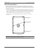
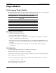
Airflow Recommendations
To ensure proper airflow, be sure that your switch is placed in a well-ventilated area and provide mini-
mum recommended clearance at the front, back and sides of the switch, as shown below. Restricted
airflow can cause your switch to overheat, which can lead to switch failure. Refer to the following import-
ant guidelines regarding airflow:
• The switch supports both Front-to-Rear and Rear-to-Front airflow depending on the fan tray and power
supplies installed. The airflow direction of the power supplies and fan tray must be the same.
• Running a mismatched fan tray or power supply will cause an error and trap to be displayed. Eventu-
ally the mismatched configuration will cause the chassis to reboot to avoid overheating.
• Follow the guidelines below regarding the minimum clearance requirements when mounting
the chassis.
Chassis Top View
Note. Clearance is not required at the top and bottom of the chassis.
}
}
Rear. 6 inches minimum
at rear of chassis.
Front. 6 inches minimum
at front of chassis.
Sides. 2 inches minimum
at left and right sides.