
User Guide


OmniAccess SafeGuard OS Administration Guide
161
Chapter 5: Setting Up SafeGuard Switches
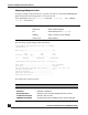
Topology Change Count.......................... 1
Topology Change in progress.................... TRUE
Interface STP Mode STP State Port Role Cost
--------- -------- ---------------- --------- ------
0/1 Enabled Forwarding Designated 20000
0/43 Enabled Forwarding Designated 20000
0/44 Enabled Discarding Backup 20000
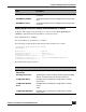
The fields in the output represent:
Field Description
Bridge Priority Configured value.
Bridge Identifier The bridge identifier for the selected MST instance. It is
made up using the bridge priority and the base MAC
address of the bridge.
Bridge Max Age Configured value.
Bridge Hold Time Minimum time between transmission of Configuration
Bridge Protocol Data Units (BPDUs).
Bridge Forward Delay Configured value.
Bridge Hello Time Configured value.
Bridge Max Hops Bridge max-hops count for the device.
Root Path Cost Value of the Root Path Cost parameter for the common
and internal spanning tree.
Root Port Identifier Identifier of the port to access the Designated Root for
the CST.
Time Since Topology
Change
Time in seconds.
Topology Change Count Number of times changed.
Topology Change In
Progress
Boolean value of the Topology Change parameter for
the switch indicating if a topology change is in progress
on any port assigned to the common and internal
spanning tree.
STP Mode The STP Mode.
STP State The STP State.
Port Role The role of the port.
Cost The port cost.