
User Guide


8
CHAPTER
2
Product Introduction OmniAccess 601
Installation Guide: 601, 602, and 604 Routers
OmniAccess 601
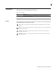
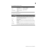
OmniAccess 601 Front Panel
The router front panel houses the system LEDs.
Figure 1 OmniAccess 601 Router Front Panel
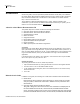
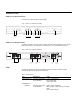
OmniAccess 601 Back Panel
The OmniAccess 601 router back panel provides connections for one WAN port, two 10/100
Base-T Ethernet ports, one AUX port, one Console port, and a 12 VDC power input jack.
Figure 2 OmniAccess 601 Router Back Panel
The OmniAccess 601 front-panel LEDs indicate real-time unit status. Table 4 provides
information about how to interpret the LED states.
Ethernet 0 LEDs Ethernet 1 LEDs
LINK/ACT HS
DUP
LINK/ACT HS
DUP
WA N Por t
LED
Power LED
Compact Flash
Fast Ethernet
Port 0
Fast Ethernet
Port 1
AUX Port
12 VDC
Input Jack
WA N Por t
Backup WAN Port
Console
Port
Table 4 LED and Port Descriptions
Port Description Color
WAN STATUS 1 Indicates traffic activity
on this interface
Green = normal activity
Red = alarm state
Yellow = test mode
ETHERNET 0 / 1
LINK/ACT Indicates traffic activity
on this interface
Green = link is operational
Blinking Yellow = either receiving or sending
traffic
Red = packet collisions
HS Indicates traffic speed
on the interface
Off = 10 Mbps
Green = 100 Mbps