D4000E_En_0607 07.6.8 11:00 ページ 1 Operating Instructions DLPTM Based Projector Commercial Use PT-D4000E ITALIANO ESPAÑOL FRANÇAIS DEUTSCH ENGLISH Model No. Read these instructions completely before operating this unit.
D4000E_En_0607 07.6.8 11:00 ページ 2 Dear Panasonic Customer: This instruction booklet provides all the necessary operating information that you might require. We hope it will help you to get the most performance out of your new product, and that you will be pleased with your Panasonic DLPTM based projector. The serial number of your product may be found on its back. You should note it in the space provided below and retain this booklet in case service is required.
D4000E_En_0607 07.6.8 11:00 ページ 3 IMPORTANT: THE MOULDED PLUG (U.K. only) FOR YOUR SAFETY, PLEASE READ THE FOLLOWING TEXT CAREFULLY. ENGLISH This appliance is supplied with a moulded three pin mains plug for your safety and convenience. A 13 amp fuse is fitted in this plug. Should the fuse need to be replaced, please ensure that the replacement fuse has a rating of 13 amps and that it is approved by ASTA or BSl to BS1362. Check for the ASTA mark or the BSl mark on the body of the fuse.
D4000E_En_0607 07.6.8 11:00 ページ 4 Contents IMPORTANT SAFETY NOTICE ..................................2 Precautions with regard to safety ............................5 Accessories ................................................................7 Precautions on handling ...........................................8 Name and function of parts.......................................9 Remote control ..................................................................9 Front and side of the projector ...............
D4000E_En_0607 07.6.8 11:00 ページ 5 Precautions with regard to safety WARNING If you notice smoke, strange smells or noise coming from the projector, disconnect the power cord plug from the wall outlet. • Do not continue to use the projector in such cases, otherwise fire or electric shocks could result. • Check that no more smoke is coming out, and then contact an Authorized Service Centre for repairs. • Do not attempt to repair the projector yourself, as this can be dangerous.
D4000E_En_0607 07.6.8 11:00 ページ 6 Precautions with regard to safety Do not set up the projector in humid or dusty places or in places where the projector may come into contact with oily smoke or steam. • Using the projector under such conditions may result in fire, electric shocks or plastic deterioration. The plastic deterioration may cause the falling down of the projector which is mounted in the ceiling. Do not place the projector on soft materials such as carpets or sponge mats.
D4000E_En_0607 07.6.8 11:00 ページ 7 If the lamp has broken, ventilate the room immediately. Do not touch or bring your face close to the broken pieces. • Failure to observe this may cause the user to absorb the gas which was released when the lamp broke and which contains nearly the same amount of mercury as fluorescent lamps, and the broken pieces may cause injury. • If you believe that you have absorbed the gas or that the gas has got into your eyes or mouth, seek medical advice immediately.
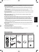
D4000E_En_0607 07.6.8 11:00 ページ 8 Precautions on handling Precautions on transport Disposal Make absolutely sure that the lens cap is in place when transporting the projector or carrying it around. Both the projector and the projection lens are precision-made and, as such, are susceptible to vibration and impacts.
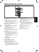
D4000E_En_0607 07.6.8 11:00 ページ 9 Name and function of parts Remote control operation indicator lamp The lamp flashes when any remote control button is pressed. POWER STANDBY ( ) button (page 22) Switched the power to the “standby” mode if the MAIN POWER has been put to the “l” position. POWER ON ( I ) button (page 21) Turns on the power if the MAIN POWER has been put to the “l” position.
D4000E_En_0607 07.6.8 11:00 ページ 10 Name and function of parts Bottom LENS (FOCUS, ZOOM, SHIFT) buttons (page 23) These buttons are used to adjust the projection lens. Function 1 (FUNC1) button (page 32) This button can control the functions set in “FUNC1” of the “OPTION1” screen from the MAIN MENU. DEFAULT button (page 26) Press this button to restore the default factory setting.
D4000E_En_0607 07.6.8 11:00 ページ 11 Front and side of the projector Status LED lights (Refer to the figure on the right.) AC IN terminal (page 21) Connect the supplied line power cord into this receptacle. Do not connect any other cable to this socket. Air filter (page 51) Security lock Attach a commercial burglar prevention cable (e.g., from Kensington) to this lock port. It is compatible with the Microsaver Security System from Kensington.
D4000E_En_0607 07.6.8 11:00 ページ 12 Name and function of parts Rear view of the main unit Controls on rear panel Controls on rear panel Air exhaust vents Do not place your hands or other objects close to the air outlet port. • Heated air comes out of the air outlet port. Do not place your hands or face, or objects which cannot withstand heat close to this port [allow at least 50 cm of space], otherwise burns or damage could result. Lamp unit cover The lamp unit is housed.
D4000E_En_0607 07.6.8 11:00 ページ 13 Side-mounted connection terminals R/PR S-VIDEO IN REMOTE 1 IN B/PB RGB 1 IN REMOTE 2 IN SYNC/HD VD IN SERIAL RGB 2 IN OUT DVI-D IN LAN OUT VIDEO IN terminal (page 20) An input terminal for video signals. (BNC) S-VIDEO IN terminal (page 20) An input terminal for S-Video signals. (MIN4-pin DIN) This terminal complies with S1 signals and automatically toggles between 16:9 and 4:3 according to the size of input signals.
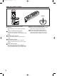
D4000E_En_0607 07.6.8 11:00 ページ 14 Using the remote control unit Loading dry cells When loading batteries into the battery compartment of the remote control, make sure that their polarities are correct. 1. Open battery compartment lid. Open the lid in the order of steps and . Effective range of remote control operation The remote control should normally be aimed at either the front or rear remote control receiver window on the projector (figure 1).
D4000E_En_0607 07.6.8 11:00 ページ 15 Setting projector ID number to remote control Every projector has its ID number and the ID number of the controlling projector must be set to the remote control in advance so that the user can operate the remote control. The ID number of the projector is set to “ALL” on shipping, and use the ID ALL button of the remote control when using only a single projector.
D4000E_En_0607 07.6.8 11:00 ページ 16 Installation Projection schemes Any of the following four projection schemes can be used depending on user’s needs or viewing conditions. Use “OPTION2” menu (chosen from the MAIN MENU) to choose the appropriate projection scheme. (page 33) FLOOR FRONT CEILING REAR (Default position) ;;; ; Installation geometry When planning the projector and screen geometry, refer to the figure below and the information on the next page for reference.
D4000E_En_0607 07.6.8 11:00 ページ 17 Projection distance by projection lens Screen aspect ratio 4:3 Model number of projection lens Throw ratio*1 Projection screen size (1.8–2.4:1) Wide-angle Wide-angle fixed-focus zoom lens lens ETET-DLE100 ET-DLE200 DLE050 (0.8:1) (1.3–1.8:1) (2.4–4.0:1) Projection distance (L) Diagonal Height Width Minimum Maximum length (SH) (SW) (LW) (LT) (SD) (L) 1.02 1.22 1.42 1.63 1.83 2.03 2.44 3.05 4.06 5.08 6.10 7.11 8.13 10.16 12.19 0.79 0.96 1.13 1.29 1.46 1.62 1.96 2.
D4000E_En_0607 07.6.8 11:00 ページ 18 Installation Calculation formulas for projection distance by lens types (L, LW, LT : m Lens type 4:3 Standard zoom lens 16:9 Wide-angle fixedfocus lens Model No. : ET-DLE050 Wide-angle zoom lens Model No. : ET-DLE100 Intermediate-focus Model No. : zoom lens ET-DLE200 Long-focus zoom lens Model No. : ET-DLE300 Ultra-long-focus zoom lens Model No.
D4000E_En_0607 07.6.8 11:00 ページ 19 Connection Setup precautions • Before connecting any of your video/audio equipment to the projector, carefully read the owners manual supplied with the equipment once again. • All cable connections should be made with the entire system devices, including the projector, first turned off. • Obtain commercial interconnecting cables for devices supplied with no accessory or optional interconnect cables.
D4000E_En_0607 07.6.
D4000E_En_0607 07.6.8 11:00 ページ 21 Projection R/PR S-VIDEO IN REMOTE 1 IN G/Y B/PB RGB 1 IN REMOTE 2 IN SYNC/HD VD IN SE OUT Powering up the projector When using an optional lens, install a projection lens before powering up the projector. (Refer to page 23.) Remove the lens cover beforehand. Connect the supplied power cord. (220 - 240 V AC, 50 Hz/60 Hz) Press the “ I ” marked side of the MAIN POWER switch to turn on the power.
D4000E_En_0607 07.6.8 11:00 ページ 22 Projection Powering off the projector Direct power off function Press the POWER STANDBY “ button. The power supplied internally causes the cooling fan to continue operating and cool off in the event that the power has failed or even after the power cord is accidentally disconnected immediately after the power has been turned off. ” Select “OK” with or button and press the ENTER button. (Or press the POWER STANDBY “ ” button again.
D4000E_En_0607 07.6.8 11:00 ページ 23 How to install and remove the projection lens How to install the projection lens Align the guide of the projection lens with the guide groove in the main unit. Turn the lens clockwise until it clicks into place. Guide groove Guide How to adjust the lens How to adjust the FOCUS, ZOOM and SHIFT The focus, zoom and up/down position of the images projected on the screen can be adjusted while the projector is positioned appropriately in relation to the screen.
D4000E_En_0607 07.6.8 11:00 ページ 24 How to adjust the lens How to adjust the lens position to the left or right When the lens left/right adjustment dial is turned clockwise, the screen moves toward the left; conversely, when it is turned counterclockwise, it moves toward the right. The maximum travel distance toward the left or right is about 10 % of the projection screen width.
D4000E_En_0607 07.6.8 11:00 ページ 25 On-screen menus Structure of menu screens Menus are extensively used for configuring, adjusting or reconfiguring the projector.
D4000E_En_0607 07.6.8 11:00 ページ 26 On-screen menus Basic menu operations Press the MENU button. The MAIN MENU appears on the screen. MAIN MENU PICTURE POSITION ADVANCED MENU DISPLAY LANGUAGE OPTION1 OPTION2 TEST PATTERN NETWORK SECURITY • Pressing the MENU button returns the screen to the previous menu page. • When the MAIN MENU is on the screen, pressing the MENU button clears all menus from the screen.
D4000E_En_0607 07.6.8 11:00 ページ 27 Adjusting the picture • For RGB signals PICTURE PICTURE MODE CONTRAST BRIGHTNESS COLOR TEMP WHITE GAIN SYSTEM DAYLIGHT VIEW SHARPNESS NOISE REDUCTION AI SYSTEM SELECTOR CONTRAST GRAPHIC 0 0 DEFAULT +10 OFF +6 1 ON AUTO “CONTRAST” is used to adjust the contrast ratio. : Raises the contrast ratio. : Lowers the contrast ratio. BRIGHTNESS “BRIGHTNESS” is used to adjust the black level. : Raises the picture brightness. : Lowers the picture brightness.
D4000E_En_0607 07.6.8 11:00 ページ 28 Adjusting the position Adjusting the picture SHARPNESS “SHARPNESS” is used to adjust the crispness of the image. : Sharpens the edge of the image. : Softens the edge of the image. POSITION SHIFT ASPECT ZOOM CLOCK PHASE KEYSTONE 4:3 +16 NOISE REDUCTION In this mode, the video noise is reduced.
D4000E_En_0607 07.6.8 11:00 ページ 29 How to use ADVANCED MENU • If the picture size is compressed or enlarged by using the 16:9 aspect ratio when the projector is used for profitable purpose or in the presence of an audience (for example, in a coffee shop or at a hotel etc.), it may infringe the rights of the copyright owner of the original picture.
D4000E_En_0607 07.6.8 11:00 ページ 30 How to use ADVANCED MENU INPUT RESOLUTION RASTER POSITION Input resolution adjustment achieves the best image when the screen flickers or halo is observed around the contour. : These select the items listed below. : These select the value. “TOTAL DOTS”, “DISPLAY DOTS”, “TOTAL LINES” and “DISPLAY LINES” Each item automatically displays a value in response to the type of the input signal.
D4000E_En_0607 07.6.8 11:00 ページ 31 OPTION1 settings USER NORMAL OFF BLUE OFF EDID2:PC 0-255:PC 1 ON You can set the colours of the screen when no signal is input to the projector. BLUE : Set screen colour to blue. BLACK : Set screen colour to black. LOGO1 : The picture registered by the user will be projected. LOGO2 : The Panasonic logo is projected. STARTUP LOGO MENU SELECT CHANGE COLOR CORRECTION OFF : This is the standard setting.
D4000E_En_0607 07.6.8 11:00 ページ 32 OPTION1 settings DVI EDID FUNC1 When the projector and external equipment are connected by DVI connection but a proper image cannot be obtained, switch this setting. EDID1 Select this mainly when external equipment (DVD player, etc.) that outputs movie video signals is connected to the DVI terminal. EDID2:PC Select this mainly when external equipment (personal computer, etc.) that outputs still image video signals is connected to the DVI terminal.
D4000E_En_0607 07.6.8 11:00 ページ 33 OPTION2 settings ALL FRONT-FLOOR LOW HORIZONTAL DUAL OFF DISABLE MENU SELECT CHANGE PROJECTOR ID The projector has an ID number setting function that helps the user to control two or more projectors either simultaneously or separately with a single remote control. The ID number is set to “ALL” by default. Hence the ID number need not be set when only one projector is used. 1 – 64 : The ID number is set in this range.
D4000E_En_0607 07.6.8 11:00 ページ 34 OPTION2 settings LAMP SELECT LAMP RELAY “LAMP SELECT” is used to choose from “SINGLE” and “DUAL” modes depending on user’s needs or viewing conditions. In “SINGLE” mode, the projector may automatically select either lamp from the 2 lamps, or the particular lamp can be specified. DUAL : Two lamps are used simultaneously. SINGLE : One of either lamps is used (lamp with shorter operating hours is automatically selected). LAMP1 : Lamp Unit 1 is always used.
D4000E_En_0607 07.6.8 11:00 ページ 35 Displaying the internal test pattern The projector’s system information can be viewed. SYSTEM INFORMATION MAIN VERSION NETWORK VERSION PROJECTOR RUNTIME LAMP1 LAMP2 LAMP1 ON LAMP2 ON 1.00.00 1.00 300h 100h 100h 20 20 RETURN The projector has eight types of internal test patterns to check the condition of the set. To display test patterns, follow the steps below. Press the TEST PATTERN button on the remote control.
D4000E_En_0607 07.6.8 11:00 ページ 36 Setting the network The settings required for the network must be established in order to use the Web browser (page 37) functions that the PC uses to control the projector. NETWORK HOST NAME DHCP IP ADDRESS SUBNET MASK GATEWAY NETWORK STATUS STORE PROJECTOR OFF 192.168. 0. 8 255.255.255. 0 192.168. 0. 1 : Make alteration if necessary when to use the DHCP server. The number of valid characters is 1 to 12 characters (spaces not allowed).
D4000E_En_0607 07.6.8 11:00 ページ 37 Using Web Browser Control This projector has networking functions which allow it to be controlled through a Web browser on a PC. The controlled items are: • Projector’s settings and adjustment • Projector’s status display • Transmission of a E-mail message when the projector has a problem Accessing from the Web browser Start the Web browser on your PC, then enter the IP address which was set in the projector. The default setting is “panasonic” (all lower case).
D4000E_En_0607 07.6.8 11:00 ページ 38 Using Web Browser Control Basic control page This page is the first page displayed when the projector is accessed through a Web browser. To move from another page, click [Projector control], then [Basic control]. Control button Click this item, and a projector control page appears. E-mail set up button Click this item, and an E-mail setting page appears. Monitor information button Click this item, and the status of the projector is displayed.
D4000E_En_0607 07.6.8 11:00 ページ 39 Detail control page Click [Projector control], then [Detail control] to display the Detail control page. On-screen status is displayed, even if the on-screen of projector is set to off. ENGLISH This button updates the on-screen description on the right of the control page with the latest information. Pressing these buttons controls the projector and updates the on-screen description on the right of the control page when control is finished.
D4000E_En_0607 07.6.8 11:00 ページ 40 Using Web Browser Control Error information page When is displayed on the status information screen, click it to display the error details. OK: Normal operation FAILED: Occurrence of trouble Note • Depending on the nature of the error, the projector may be placed in the standby mode for its own protection.
D4000E_En_0607 07.6.8 11:00 ページ 41 E-mail set up page With this projector, if a problem occurs or if the lamp usage time reaches a set value, an E-mail message can be sent to one or more preset E-mail addresses (maximum two addresses). Click [Projector control], then [E-mail set up] to display the E-mail set up page. Select “Enable” to use the E-mail function. Enter the IP address or server name of the E-mail server (SMTP). The DNS server must be set if the server name is entered.
D4000E_En_0607 07.6.8 11:00 ページ 42 Using Web Browser Control E-mail set up page (Continuing) Enter the E-mail address to which the E-mail is to be sent when two E-mail addresses are going to be used. Do not enter it when the second E-mail address is not going to be used. Check these boxes when E-mail is to be sent periodically to two E-mail addresses. E-mail will be sent at the times and on the days checked. Button to update settings Select the conditions for sending the second E-mail.
D4000E_En_0607 07.6.8 11:00 ページ 43 DNS server set up page Click [Network set up], then [DNS server set up] to display the DNS server set up page. Primary DNS server address Available input characters: numbers (0 - 9), period (.) (ex. 192.168.0.253) Secondary DNS server address Available input characters: numbers (0 - 9), period (.) (ex. 192.168.0.
D4000E_En_0607 07.6.8 11:00 ページ 44 Using Web Browser Control Contents of mail sent • Mail with the contents shown below is sent when the E-mail settings have been established. • Mail with the contents shown below is sent when an error has occurred.
D4000E_En_0607 07.6.8 11:00 ページ 45 Network config page Click [Network set up], then [Network config] to display the Network config page. Set this to ON to enable the DHCP client function. Enter the IP address if DHCP server is not used. Enter the subnet mask if DHCP server is not used. ENGLISH Enter the gateway address if DHCP server is not used. Enter the name of the projector here. Enter the host name here if it is required when the DHCP server is going to be used, for instance.
D4000E_En_0607 07.6.8 11:00 ページ 46 Using the PJLink™ protocol The network functions of the projector are compatible with PJLink™ Class 1. The operations mentioned below can be performed from a personal computer using the PJLink™ protocol. • Projector settings • Projector status inquiry Supported commands The commands for controlling the projector using the PJLink™ protocol are as given in the table below.
D4000E_En_0607 07.6.8 11:00 ページ 47 Setting the security PASSWORD INPUT SET (When using the projector for the first time) Press the , , , , , , and buttons in this order, and press the ENTER button. (When the password has been changed) Input the new password, and press the ENTER button. PASSWORD It is possible to display the password input screen each time the power is turned on. If this option is used, no operations except for the POWER button can be performed without inputting the correct password.
D4000E_En_0607 07.6.8 11:00 ページ 48 Using the serial terminals The main unit is equipped with SERIAL terminals located in its terminal section on the side, and this terminal is compliant with RS-232C. Also a serial output terminal is provided to enable plural projector control.
;; ; D4000E_En_0607 07.6.8 11:00 ページ 49 Using the REMOTE 2 terminal Control commands When controlling the projector from a computer, the following commands are available: Power “ON” Power “STANDBY” PON POF Power query QPW IIS Switch input modes Query for active lamp mode QSL Active lamp mode LPM Note Example of a control panel layout Function of command Remarks To confirm that the power is ON, use a “Power query” command.
D4000E_En_0607 07.6.8 11:00 ページ 50 Indication of lamp monitor This projector is equipped with 3 indicators to show when a lamp needs replacement or there is an abnormal internal temperature. These lamps flash or light up to indicate a problem. Turn the power off and follow the steps below.
D4000E_En_0607 07.6.8 11:00 ページ 51 Cleaning and replacement of air filter If too much dust accumulates on the air filter, [CLEAN THE AIR FILTER]* appears at the lower left of the screen, and the temperature monitor (TEMP) will blink once. If even more dust is allowed to accumulate, the temperature inside the main unit will rise, the temperature monitor (TEMP) will blink twice, and the power is turned off.
D4000E_En_0607 07.6.8 11:00 ページ 52 Replacing the lamp unit WARNING! When replacing the lamp, allow it to cool for at least one hour before handling it. • The lamp cover gets very hot, and touching it can cause burns. Make sure that two lamp units are always installed. Precautions on lamp unit replacement Remove the power plug and confirm that the surroundings of the lamp unit have cooled off. Be careful when handling a light source lamp. The lamp unit has high internal pressure.
D4000E_En_0607 07.6.8 11:00 ページ 53 Lamp unit replacement steps Turn the power off by following the steps on page 22, remove the power plug and confirm that the surroundings of the lamp unit have cooled off. Check that the fan has stopped running. Have a Phillips screwdriver ready ahead of time. Remove the screw securing the lamp unit cover, and then slide the lamp unit cover a little toward the left, and remove it.
D4000E_En_0607 07.6.8 11:00 ページ 54 Ceiling Mount Bracket Safeguards The followings are included with the other accessories. Wire cable (x 1) [TTRA0146] Wire fastening M6 screw (x 1) [XYN6+F10FJ] The projector and the ceiling mount bracket are designed sufficiently safety though, make sure the safety cable provided with the projector is installed and attached to the bottom of the projector when mounting in the ceiling for safety and security.
D4000E_En_0607 07.6.8 11:00 ページ 55 Before asking for service --- check the following points.
D4000E_En_0607 07.6.8 11:00 ページ 56 Specifications Model No. Power supply Power consumption Amps DLPTM panel Panel size Display system Number of pixels Lens Powered zoom Powered focus control Projection lamp Optical output Applicable scanning frequency For Video signal (S-Video included) For RGB signal For DVI-D signal For YPBPR signal Colour system Screen size Screen aspect ratio PT-D4000E AC 220 - 240 V, 50 Hz/60 Hz 520 W (about 15 W in standby without fan running) 2.7 A 0.
D4000E_En_0607 07.6.8 11:00 ページ 57 PT-D4000E Model No. Video input terminal S-Video input terminal Serial input/output terminal Remote1 input/output terminal Remote2 input terminal DVI-D input terminal LAN terminal 1 set of high-density, D-Sub 15-pin (female) [For YPBPR input] Y: 1.0 V [p-p] synchronization signal included, PBPR: 0.7 V[p-p] 75 Ω [For RGB input] 0.7 V[p-p] 75 Ω For G-SYNC: 1.
D4000E_En_0607 07.6.8 11:00 ページ 58 Compatible Signal List Resolution (as a number of dots)*1 Display mode NTSC/NTSC4.
D4000E_En_0607 07.6.8 11:01 ページ 59 Dimensions unit : mm 478.5 R3 441 S-VIDEO IN REMOTE 1 IN G/Y B/PB RGB 1 IN REMOTE 2 IN SYNC/HD VD IN SERIAL RGB 2 IN OUT DVI-D IN LAN 157 167 R/PR VIDEO IN ENGLISH 4 12 368 425 0 OUT TBMU448 86.
D4000E_En_0607 07.6.8 11:01 ページ 60 Information on Disposal for Users of Waste Electrical & Electronic Equipment (private households) This symbol on the products and/or accompanying documents means that used electrical and electronic products should not be mixed with general household waste. For proper treatment, recovery and recycling, please take these products to designated collection points, where they will be accepted on a free of charge basis.