ACT 250 TURBOMOLECULAR PUMP CONTROLLER FOR ATP 150 AND ATP 400 ATP Series User’s Manual addendum
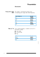
Contents ACT 250 addendum Presentation ■ The ACT 250 controller . . . . . . . . . . . . . . ■ p. 3 ■ Main characteristics . . . . . . . . . . . . . . . . ■ p. 3 ■ Accessories. . . . . . . . . . . . . . . . . . . . . . ■ p. 4 ■ Pump supply cable ■ “End-user” kit ■ Control modes for ACT 250 “box” controller . . . . . . . . . . . . . . . . . . . . . . . ■ p. 5 ■ Local control mode ■ Remote control ■ Control modes for ACT 250 “OEM” controller . . . . . . . . . . . . . . . . . . . . . . . ■ p.
Contents ACT 250 addendum Commissioning (continued) ■ RS 232/485 serial link . . . . . . . . . . . . . . ■ p. 14 ■ Wiring the RS 232 or RS 485 serial link ■ Configuring the RS 232 or RS 485 serial link ■ Use ■ Detailed description of RS commands. . . . . . ■ p. 15 ■ Syntax conventions applicable to all commands Use ■ Controlling the pump from the ACT 250 controller . . . . . . . . . . . . . . . . . ■ p. 24 January 2001 ■ Controller functions. . . . . . . . . . . . . . . . . ■ p.
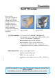
Presentation The ACT 250 controller Dear Customer, You have just bought an ACT 250 controller. In order to ensure the best possible performance of the equipment and your complete satisfaction in using it, we advise you to read this addendum carefully before attempting to service or use your controller. ACT 250 controller Insertable “box” version Part No. 108320 Integrable “OEM” version Part No.
Presentation Accessories Pump power supply cable “End-user” kit The controller is connected to the pump using a corresponding power supply cable, ordered separately. Cable length (m) 1 1.5 3.5 5 Part No. 105086 A458885 101812 101810 10 15 20 101811 105303 A458478 This kit, ordered separately, is needed to use the ACT in local mode. It includes: ■ 1 mains cable, ■ 1 connector plug, ■ 4 legs. Part No.
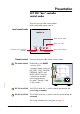
Presentation ACT 250 “box” controller control modes There are two possible control modes: local control and remote control.
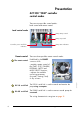
Presentation ACT 250 “OEM” controller control modes There are two possible control modes: local control and remote control.
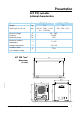
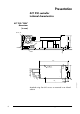
Presentation ACT 250 controller technical characteristics Characteristic Weight Dimensions H x W x D Unit kg mm Nominal voltage Frequency Maximum power Maximum ambient temperature V Hz W Storage temperature Customer mains circuit breaker rating ACT 250 “box” ACT 250 “OEM” 1.8 1.3 128.4 × 10⁶.
Presentation ACT 250 controller technical characteristics ACT 250 “OEM” dimensions (in mm) 95 maxi. RS232/485 POWER SUPPLY 8 mini.
Commissioning Safety instructions January 2001 Before switching on the controller, the user should study the manual and follow the safety instructions listed in the compliance certificate booklet supplied with the pump. See sheet B10 in the ATP pump User Manual.
Commissioning ACT 250 controller electrical connections If the controller is remote controlled, make the various connections on the REMOTE connector (see page 13 for wiring details). ■ If the controller is used in local mode, the pump can only operate if the connector plug (ordered separately) is connected to the REMOTE connector (see page 13 for wiring details).
Commissioning ACT 250 remote connector characteristics When units containing the control circuits are equipped with dry contact outputs, it is the customer's responsibility to use the outputs in compliance with safety regulations. Voltage control mode 6 1 11 12 13 14 10 15 5 +15 V Principle of voltagecontrolled optocoupled inputs 0V The inputs are activated when an AC or DC voltage is applied. The voltage should be between 15 and 24 Volts. (15-pin Sub-D female connector).
Commissioning ACT 250 remote connector characteristics Signalling on output contacts These are dry contacts (48 V AC - 1 A) which replicate pump status information.
Commissioning ACT 250 remote connector wiring Use in local mode ■ Standard connector plug (factory wired) 6 1 11 12 Wiring seen from solder side 10 15 5 Use in remote control mode ■ With galvanic isolation (recommended) Wiring seen from solder side. compulsory screen 6 1 11 customer device 15 V –> 24 V 12 ➞ Select. Mode 13 ➞ Standby Mode 14 10 5 ➞ Start/Stop 15 ➞ Common for inputs ACT unit ground ■ ➞ Ext.
Commissioning RS 232 / 485 serial link Wiring the RS 232 or RS 485 serial link Configuring the RS 232 or RS 485 serial link See sheet B 110 in the ATP Series Pump User Manual. The link is configured using switches on the rear panel of the controller.
Commissioning Detailed description of RS commands Syntax conventions applicable to all commands Status values Error messages ADR Syntax adr = address, from 000 to 255 Carriage Return (ascii 13) Line Feed (ascii 10); shown in brackets as it is not compulsory. ok : command executed correctly Err0 Err1 Err2 Err3 Err4 : : : : : adjustment error (out of bounds) command error (syntax) parameter error (e.g.
Commissioning Detailed description of RS commands CKS Syntax Enables or disables checksums on reply strings #adrCKSON[] Enables the ASCII checksum character at the end of a reply string or #adrCKSOFF[] Disables the ASCII checksum character at the end of a reply string Result #adr,ok,S #adr,ok for CKSON for CKSOFF This feature enables the user to test whether a transmission error has occurred for the reply string.
Commissioning Detailed description of RS commands DLI Syntax Defines the DataLogger transmission interval #adrDLIxxx[] xxx: DataLogger transmission interval in seconds condition: 001 ≤ xxx ≤ 255 Result See also: DLR DLR Syntax Result #adr,ok or Err2 Note: if ok, the interval sent is stored in user memory. Enables DataLogger operation (RS232 only) #adrDLR[] #adr,sssss,nnnnn,iiii,ttttt,uuuu.
Commissioning Detailed description of RS commands ECH Syntax Enables or disables command echoing #adrECHON[] enables all characters received to be echoed over the serial port or #adrECHOFF[] disables characters received from being echoed over the serial port. Result #adr,ok Comments: - This command is disabled in RS 485 operation, the value OFF is required. - Using a loop-type RS 232 network requires “ECHON”.
Commissioning Detailed description of RS commands LEV Syntax Result Returns the state of the parameters defined by SET #adrLEV[] #adr,nnnnn,sssss,aaaa,hhhhh or #adr,nnnnn rpm,sssss rpm,aaaa mA,hhhhh hours Returns the current values: nnnnn : speed set point sssss : stand-by speed aaaa : max.
Commissioning Detailed description of RS commands OPT Syntax Used to select possible user choices #adrOPT2 n[] choice of temperature unit: n = 0 : degrees Centigrade n = 1 : degrees Fahrenheit Result See also: SEL RPM Syntax Result #adr,ok Comment: The choice of the temperature unit affects the results of the DLR and STA strings.
Commissioning Detailed description of RS commands SBY Syntax Result See also: NSP, RPM SEL Syntax Result Switches the speed set point to the stand-by value #adrSBY[] #adr,ok Resets the stand-by speed to its last stored value, and allows it to be modified if an “RPM” command is sent. This configuration is automatically stored in user memory.
Commissioning Detailed description of RS commands SET Syntax Result See also: LEV SHT Syntax Result Defines the internal operating parameters #adrSET1 hhhhh[] : maintenance time limit 000[] #adr,ok The strings sent following DLR, LEV and SPD commands are sent without parameter identification sub-strings (e.g. without units).
Commissioning Detailed description of RS commands STA Syntax Result Returns the status of the internal dynamic parameters #adrSTA[] #adr,xxxxxx,yyyyyy,zzzzzz,sssss,iiii,www,ppp,vvv,ttttt adr: address 543210 xxxxxx status bits: 5 - RS echo (1->off) 4 - String long (0) / short (1) 3 - On (1) / Off (0) 2 - reduced or nominal speed reached(1) 1 - standby (1) 0 - running-in (1) yyyyyy fault bits: 5 - variator temperature 4 - motor temperature 3 - excess current 2 - sensors or start-up 1 - ext
Use Controlling the pump from the ACT 250 controller Once all connections are complete, plug the controller into the mains. Indicator lights “box” version POWER FAULT SPEED START STOP ACT 250 Yellow lit Controller on Red lit Controller fault Red flashing Controller alert Yellow lit Green flashing pump rotation The pump rotation speed is speed accelerating greater than the selected speed (speed reduction during operation) Green lit The pump has attained the selected speed.
Use Controlling the pump from the ACT 250 controller Starting the pump with the START switch START Stopping the pump with the STOP switch The pump is started up to reach the selected speed. The yellow rising speed indicator light comes on. When the pump reaches its selected speed, the yellow indicator light goes off and the green indicator light comes on. The rotation speed monitoring indicator lights go off. The pump motor is no longer powered, the pump decelerates.
Use Controller functions Precautions Local mode operation The “OEM” version of the ACT 250 has been designed with electrical safety and electromagnetic compatibility standards in mind. It is the user’s responsibility to provide external shielding to comply with EMC and electrical safety standards. The Start and Stop functions use switches located on the front panel of the “box” version and on the board for the “OEM” version.
Use Controller functions Fault monitoring Alerts are indicated by: - flashing red indicator. The pump power supply is maintained. ■ Faults are indicated by: - lit red indicator. The pump is stopped as soon as a fault is detected. ■ Alerts and faults shown by the indicator light include: - controller overheating, - pump motor overheating, - cable disconnected (pump / controller) - external safety device open, - overcurrent on speed variator.
France Alcatel Vacuum Technology - France 98, avenue de Brogny - BP 2069 74009 ANNECY - Cedex Tel : (33) 4 50 65 77 77 Fax : (33) 4 50 65 77 89 Germany Alcatel Hochvakuum Technik GmbH Am Kreuzeck 10 D – 97877 WERTHEIM Tel: (49) 9342 96100 Fax: (49) 9342 961030 Italy Alcatel Vacuum Systems S.p.