
Product Manual


40402 & 40403 Assembly Instructions
Page 15
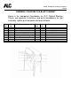
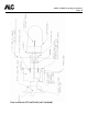
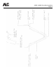
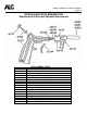
ASSEMBLY DIAGRAM FOR DUST COLLECTOR
Below is the component breakdown for ALC 100 CFM dust
collector. The dust collector is assembled and ready for use. Dust
collector hose is located in the bottom drum of the collector and
must be removed and attached to dust collector and cabinet.
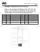
Item No.
Part No. Description Item No. Part No. Description
1 11568 Cap for dust collector 6 11567 Motor screen
1 10759 Protective edging 7 40287 Vacuum motor
2 11637 Switch 8 11602 Motor support bracket
3 11012 Connector 9 11564P Top drum
3 11008 Electric cord 10 N/A
4 40267
SM
Filter bag 11 11565P Bottom drum
5 n/a 12 11575 Dust Collector Hose 2 ¼”
x 6”