
Use and Care Manual


40001, 40003, 40004, 40005 Assembly Instructions
Page 12
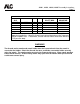
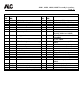
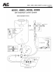
PARTS LIST
ITEM
NO.
PART
NO.
DESCRIPTION
ITEM
NO.
PART
NO.
DESCRIPTION
1
40224
0-200 psi pressure gauge
23
40225
6” wheels (40001 only)
2
40219
1/2” x 1/4” bushing
24
40226
8” wheels (40003 and 40004)
3
40221
1/2” cross
25
40227
10” wheels (40005 only)
4
40213
1/2” x close nipples
26
40231
1-1/2” x 1/2” bushing (40005)
5
40198
1/2” bronze ball valve
27
40166
Complete deadman handle
6
40186
1/2” brass adapter
29
40230
1/2” tee
7
10935
Hose clamp
30
40209
2-prong quick disconnect
coupling (40004 and 40005)
8
40123
Red by-pass hose
31
40210
2-prong hose connection (40004
and 40005)
9
40217
3/4” x 1/2” bushing
32
40216
1/2” 90 elbow
10
40199
1/2” ball valve (pressure relieving)
33
40117
1/2” abrasive hose (40001 and
40003)
11
40192
1/2” hose adaptor
40118
1/2” abrasive hose (40004)
12
10905
1/2” hose clamp
40120
1/2” abrasive hose (40005)
13
40223
1/2” plug
34
40173
Shoulder bolt with nut
14
40170
Nozzle base with bracket
35
40228
Closure gasket
15
40196
Nozzle washer
36
40279
65# pressure tank only
16
40193
Nozzle retainer nut
40281
110# pressure tank only
17
Nozzle–see pg. 4 for size/part no.
40282
150# pressure tank only
18
40164
Sealing block
40286
300# pressure tank only
19
40165
Nut and bolt assembly
37
40232
Axle bolt assy. (40001, 40003,
40004)
20
40168
Handle
38
10973
5/8” diameter axle (F-300)
21
11500
Pivot tension spring
39
10974
Palnuts for S-40 axle
22
40207
1/2” moisture separator (optional)
40
40229
Pressure relief valve
Moisture separator is standard on models 40004 and 40005. It is optional for models 40001 and 40003.