bdi GDB JTAG interface for GNU Debugger ARM11 / Cortex-A8 User Manual Manual Version 1.
bdiGDB for GNU Debugger, BDI2000 (ARM11/Cortex-A8) User Manual 2 1 Introduction ................................................................................................................................. 4 1.1 BDI2000................................................................................................................................. 4 1.2 BDI Configuration .................................................................................................................. 5 2 Installation .
bdiGDB for GNU Debugger, BDI2000 (ARM11/Cortex-A8) User Manual 3 7 Appendices A Troubleshooting ........................................................................................................................ 51 B Maintenance .............................................................................................................................. 52 C Trademarks ................................................................................................................................
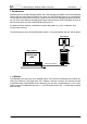
bdiGDB for GNU Debugger, BDI2000 (ARM11/Cortex-A8) User Manual 4 1 Introduction bdiGDB enhances the GNU debugger (GDB), with JTAG debugging for ARM11 and Cortex-A8 based targets. With the builtin Ethernet interface you get a very fast download speed of up to 200 Kbytes/ sec. No target communication channel (e.g. serial line) is wasted for debugging purposes. Even better, you can use fast Ethernet debugging with target systems without network capability.
bdiGDB for GNU Debugger, BDI2000 (ARM11/Cortex-A8) User Manual 5 1.2 BDI Configuration As an initial setup, the IP address of the BDI2000, the IP address of the host with the configuration file and the name of the configuration file is stored within the flash of the BDI2000. Every time the BDI2000 is powered on, it reads the configuration file via TFTP.
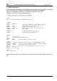
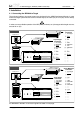
bdiGDB for GNU Debugger, BDI2000 (ARM11/Cortex-A8) User Manual 6 2 Installation 2.1 Connecting the BDI2000 to Target The enclosed cables to the target system are designed for the ARM Development Boards. In case where the target system has the same connector layout, the cable (14 pin or 20 pin) can be directly connected. ! In order to ensure reliable operation of the BDI (EMC, runtimes, etc.) the target cable length must not exceed 20 cm (8"). Rev.
bdiGDB for GNU Debugger, BDI2000 (ARM11/Cortex-A8) User Manual 7 BDI MAIN / TARGET A Connector Signals Pin Name Describtion 1 reserved This pin is currently not used. 2 TRST JTAG Test Reset This open-drain / push-pull output of the BDI2000 resets the JTAG TAP controller on the target. Default driver type is open-drain. 3+5 GND System Ground 4 TCK JTAG Test Clock This output of the BDI2000 connects to the target TCK line.
bdiGDB for GNU Debugger, BDI2000 (ARM11/Cortex-A8) User Manual 8 2.1.1 Changing Target Processor Type Before you can use the BDI2000 with an other target processor type (e.g. ARM <--> PPC), a new setup has to be done (see chapter 2.5). During this process the target cable must be disconnected from the target system. The BDI2000 needs to be supplied with 5 Volts via the BDI OPTION connector (Rev. A) or via the POWER connector (Rev. B/C). For more information see chapter 2.2.1 «External Power Supply»).
bdiGDB for GNU Debugger, BDI2000 (ARM11/Cortex-A8) User Manual 9 2.1.2 Adaptive Clocking Adaptive clocking is a feature which ensures that the BDI2000 never loses synchronization with the target device, whatever the target clock speed is. To achieve this, BDI2000 uses two signals TCK and RTCK. When adaptive clocking is selected, BDI2000 issues a TCK signal and waits for the Returned TCK (RTCK) to come back. BDI2000 does not progress to the next TCK until RTCK is received.
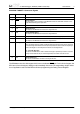
bdiGDB for GNU Debugger, BDI2000 (ARM11/Cortex-A8) User Manual 10 BDI TARGET B Connector Signals: Pin Name Describtion 1 TDO JTAG Test Data Out This input to the BDI2000 connects to the target TDO line. 2 reserved 3 TDI 4 reserved 5 RTCK Returned JTAG Test Clock This input to the BDI2000 connects to the target RTCK line. 6 Vcc Target 1.8 – 5.0V: This is the target reference voltage.
bdiGDB for GNU Debugger, BDI2000 (ARM11/Cortex-A8) User Manual 11 2.2 Connecting the BDI2000 to Power Supply 2.2.1 External Power Supply The BDI2000 needs to be supplied with 5 Volts (max. 1A) via the BDI OPTION connector (Rev. A) or via POWER connector (Rev. B/C). The available power supply from Abatron (option) or the enclosed power cable can be directly connected. In order to ensure reliable operation of the BDI2000, keep the power supply cable as short as possible.
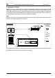
bdiGDB for GNU Debugger, BDI2000 (ARM11/Cortex-A8) User Manual 12 2.2.2 Power Supply from Target System The BDI2000 needs to be supplied with 5 Volts (max. 1A) via BDI MAIN target connector (Rev. A) or via TARGET A connector (Rev. B/C). This mode can only be used when the target system runs with 5V and the pin «Vcc Target» is able to deliver a current up to 1A@5V. For pin description and layout see chapter 2.1 «Connecting the BDI2000 to Target». Insert the enclosed Jumper as shown in figure below.
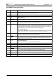
bdiGDB for GNU Debugger, BDI2000 (ARM11/Cortex-A8) User Manual 13 2.3 Status LED «MODE» The built in LED indicates the following BDI states: Rev. A BDI TRGT MODE BDI MAIN BDI OPTION Rev. B/C BDI TRGT MODE TARGET A MODE LED TARGET B BDI STATES OFF The BDI is ready for use, the firmware is already loaded. ON The power supply for the BDI2000 is < 4.75VDC. BLINK The BDI «loader mode» is active (an invalid firmware is loaded or loading firmware is active).
bdiGDB for GNU Debugger, BDI2000 (ARM11/Cortex-A8) User Manual 14 2.4 Connecting the BDI2000 to Host 2.4.1 Serial line communication Serial line communication is only used for the initial configuration of the bdiGDB system. The host is connected to the BDI through the serial interface (COM1...COM4). The communication cable (included) between BDI and Host is a serial cable. There is the same connector pinout for the BDI and for the Host side (Refer to Figure below). Rev.
bdiGDB for GNU Debugger, BDI2000 (ARM11/Cortex-A8) User Manual 15 2.4.2 Ethernet communication The BDI2000 has a built-in 10 BASE-T Ethernet interface (see figure below). Connect an UTP (Unshilded Twisted Pair) cable to the BD2000. For thin Ethernet coaxial networks you can connect a commercially available media converter (BNC-->10 BASE-T) between your network and the BDI2000. Contact your network administrator if you have questions about the network. Rev.
bdiGDB for GNU Debugger, BDI2000 (ARM11/Cortex-A8) User Manual 16 2.5 Installation of the Configuration Software On the enclosed diskette you will find the BDI configuration software and the firmware required for the BDI2000. For Windows NT users there is also a TFTP server included. The following files are on the diskette. b20a11gd.exe Windows configuration program b20a11gd.hlp Windows help file for the configuration program b20a11gd.xxx Firmware for the BDI2000 armjed20.
bdiGDB for GNU Debugger, BDI2000 (ARM11/Cortex-A8) User Manual 17 2.5.1 Configuration with a Linux / Unix host The firmware / logic update and the initial configuration of the BDI2000 is done with a command line utility. In the ZIP Archive bdisetup.zip are all sources to build this utility. More information about this utility can be found at the top in the bdisetup.c source file. There is also a make file included. Starting the tool without any parameter displays information about the syntax and parameters.
bdiGDB for GNU Debugger, BDI2000 (ARM11/Cortex-A8) User Manual 18 4. Transmit the initial configuration parameters: With "bdisetup -c" the configuration parameters are written to the flash memory within the BDI. The following parameters are used to configure the BDI: BDI IP Address The IP address for the BDI2000. Ask your network administrator for assigning an IP address to this BDI2000. Every BDI2000 in your network needs a different IP address.
bdiGDB for GNU Debugger, BDI2000 (ARM11/Cortex-A8) User Manual 19 2.5.2 Configuration with a Windows host First make sure that the BDI is properly connected (see Chapter 2.1 to 2.4). ! To avoid data line conflicts, the BDI2000 must be disconnected from the target system while programming the logic for an other target CPU (see Chapter 2.1.1).
bdiGDB for GNU Debugger, BDI2000 (ARM11/Cortex-A8) User Manual 20 BDI IP Address Enter the IP address for the BDI2000. Use the following format: xxx.xxx.xxx.xxx e.g.151.120.25.101 Ask your network administrator for assigning an IP address to this BDI2000. Every BDI2000 in your network needs a different IP address. Subnet Mask Enter the subnet mask of the network where the BDI is connected to. Use the following format: xxx.xxx.xxx.xxxe.g.255.255.255.0 A subnet mask of 255.255.255.
bdiGDB for GNU Debugger, BDI2000 (ARM11/Cortex-A8) User Manual 21 2.6 Testing the BDI2000 to host connection After the initial setup is done, you can test the communication between the host and the BDI2000. There is no need for a target configuration file and no TFTP server is needed on the host. • If not already done, connect the bdiGDB system to the network. • Power-up the BDI2000. • Start a Telnet client on the host and connect to the BDI2000 (the IP address you entered during initial configuration).
bdiGDB for GNU Debugger, BDI2000 (ARM11/Cortex-A8) User Manual 22 3 Using bdiGDB 3.1 Principle of operation The firmware within the BDI handles the GDB request and accesses the target memory or registers via the JTAG interface. There is no need for any debug software on the target system. After loading the code via TFTP debugging can begin at the very first assembler statement.
bdiGDB for GNU Debugger, BDI2000 (ARM11/Cortex-A8) User Manual 23 3.2 Configuration File The configuration file is automatically read by the BDI2000 after every power on. The syntax of this file is as follows: ; comment [part name] core# identifier parameter1 core# identifier parameter1 ..... [part name] core# identifier parameter1 core# identifier parameter1 ..... etc. parameter2 ..... parameterN parameter2 ..... parameterN ; comment parameter2 ..... parameterN parameter2 .....
bdiGDB for GNU Debugger, BDI2000 (ARM11/Cortex-A8) User Manual 24 3.2.1 Part [INIT] The part [INIT] defines a list of commands which are be executed every time the target comes out of reset (except in STARTUP RUN mode). The commands are used to get the target ready for loading the program file. WGPR register value Write value to the selected general purpose register. register the register number 0 ..
bdiGDB for GNU Debugger, BDI2000 (ARM11/Cortex-A8) User Manual 25 WBIN address filename Write a binary image to the selected memory place. The binary image is read via TFTP from the host. Up to 4 such entries are supported. address the memory address filename the filename including the full path Example: WBIN 0x4000 pagetable.bin RM8 address value Read a byte (8bit) from the selected memory place.
bdiGDB for GNU Debugger, BDI2000 (ARM11/Cortex-A8) User Manual 26 Using a startup program to initialize the target system: For targets where initialization can not be done with a simple initialization list, there is the possibility to download and execute a special startup code. The startup code must be present in a file on the host. The last instruction in this startup code should be a BKPT. After processing the initlist, the BDI downloads this startup code to RAM, starts it and waits until it completes.
bdiGDB for GNU Debugger, BDI2000 (ARM11/Cortex-A8) User Manual 27 3.2.2 Part [TARGET] The part [TARGET] defines some target specific values. CPUTYPE type This value gives the BDI information about the connected CPU. type The CPU type from the following list: ARM1136, CORTEX-A8, OMAP3430 Example: CPUTYPE ARM1136 CLOCK main [init] [SLOW]With this value(s) you can select the JTAG clock rate the BDI2000 uses when communication with the target CPU.
bdiGDB for GNU Debugger, BDI2000 (ARM11/Cortex-A8) User Manual 28 STARTUP mode [runtime] This parameter selects the target startup mode. The following modes are supported: HALT This default mode tries to forces the target to debug mode immediately out of reset. If successful, no code is executed after reset. STOP In this mode, the BDI lets the target execute code for "runtime" milliseconds after reset. This mode is useful when monitor code should initialize the target system.
bdiGDB for GNU Debugger, BDI2000 (ARM11/Cortex-A8) BREAKMODE mode User Manual 29 This parameter defines how breakpoints are implemented. SOFT This is the normal mode. Breakpoints are implemented by replacing code with a BKPT instruction. HARD In this mode, the breakpoint hardware is used. Only 6 breakpoints at a time are supported. Example: BREAKMODE HARD MEMACCES mode [wait] For Cortex-A8, this parameter defines how memory is accessed.
bdiGDB for GNU Debugger, BDI2000 (ARM11/Cortex-A8) User Manual 30 Daisy chained JTAG devices: For ARM targets, the BDI can also handle systems with multiple devices connected to the JTAG scan chain. In order to put the other devices into BYPASS mode and to count for the additional bypass registers, the BDI needs some information about the scan chain layout. Enter the number (count) and total instruction register (irlen) length of the devices present before the ARM chip (Predecessor).
bdiGDB for GNU Debugger, BDI2000 (ARM11/Cortex-A8) User Manual 31 Low level JTAG scan chain configuration: Sometimes it is necessary to configure the test access port (TAP) of the target before the ARM debug interface is visible and accessible in the usual way. The BDI supports this configuration in a very generic way via the SCANINIT and SCANPOST configuration commands. Both accept a string that defines the JTAG sequences to execute.
bdiGDB for GNU Debugger, BDI2000 (ARM11/Cortex-A8) User Manual 32 3.2.3 Part [HOST] The part [HOST] defines some host specific values. IP ipaddress The IP address of the host. ipaddress the IP address in the form xxx.xxx.xxx.xxx Example: IP 151.120.25.100 FILE filename The default name of the file that is loaded into RAM using the Telnet ’load’ command. This name is used to access the file via TFTP. If the filename starts with a $, this $ is replace with the path of the configuration file name.
bdiGDB for GNU Debugger, BDI2000 (ARM11/Cortex-A8) User Manual 33 PROMPT string This entry defines a new Telnet prompt. The current prompt can also be changed via the Telnet interface. Example: PROMPT ARM11> DUMP filename The default file name used for the DUMP command from a Telnet session. filename the filename including the full path Example: DUMP dump.bin TELNET mode By default the BDI sends echoes for the received characters and supports command history and line editing.
bdiGDB for GNU Debugger, BDI2000 (ARM11/Cortex-A8) User Manual 34 3.2.4 Part [FLASH] The Telnet interface supports programming and erasing of flash memories. The bdiGDB system has to know which type of flash is used, how the chip(s) are connected to the CPU and which sectors to erase in case the ERASE command is entered without any parameter. CHIPTYPE type This parameter defines the type of flash used. It is used to select the correct programming algorithm.
bdiGDB for GNU Debugger, BDI2000 (ARM11/Cortex-A8) User Manual 35 ERASE addr [increment count] [mode [wait]] The flash memory may be individually erased or unlocked via the Telnet interface. In order to make erasing of multiple flash sectors easier, you can enter an erase list. All entries in the erase list will be processed if you enter ERASE at the Telnet prompt without any parameter. This list is also used if you enter UNLOCK at the Telnet without any parameters.
bdiGDB for GNU Debugger, BDI2000 (ARM11/Cortex-A8) User Manual 36 Supported Flash Memories: There are currently 3 standard flash algorithm supported. The AMD, Intel and Atmel AT49 algorithm. Almost all currently available flash memories can be programmed with one of this algorithm. The flash type selects the appropriate algorithm and gives additional information about the used flash.
bdiGDB for GNU Debugger, BDI2000 (ARM11/Cortex-A8) User Manual 37 Note: Some Intel flash chips (e.g. 28F800C3, 28F160C3, 28F320C3) power-up with all blocks in locked state. In order to erase/program those flash chips, use the init list to unlock the appropriate blocks: WM16 WM16 WM16 WM16 WM16 0xFFF00000 0xFFF00000 0xFFF10000 0xFFF10000 ....
bdiGDB for GNU Debugger, BDI2000 (ARM11/Cortex-A8) User Manual 38 3.2.5 Part [REGS] In order to make it easier to access target registers via the Telnet interface, the BDI can read in a register definition file. In this file, the user defines a name for the register and how the BDI should access it (e.g. as memory mapped, memory mapped with offset, ...). The name of the register definition file and information for different registers type has to be defined in the configuration file.
bdiGDB for GNU Debugger, BDI2000 (ARM11/Cortex-A8) User Manual 39 Example for a register definition: Entry in the configuration file: [REGS] FILE E:\cygwin\home\bdidemo\arm\reg1136.def The register definition file: ; ;Coprocessor Register Numbers: ; ; +-----+-+-------+-----+-+-------+ ; |opc_2|0| CRm |opc_1|0| nbr | ; +-----+-+-------+-----+-+-------+ ; ;The 16bit register number is used to build the appropriate MCR/MRC instruction.
bdiGDB for GNU Debugger, BDI2000 (ARM11/Cortex-A8) User Manual 40 3.3 Debugging with GDB Because the target agent runs within BDI, no debug support has to be linked to your application. There is also no need for any BDI specific changes in the application sources. Your application must be fully linked because no dynamic loading is supported. 3.3.1 Target setup Target initialization may be done at two places. First with the BDI configuration file, second within the application.
bdiGDB for GNU Debugger, BDI2000 (ARM11/Cortex-A8) User Manual 41 3.3.3 Breakpoint Handling There are two breakpoint modes supported. One of them (SOFT) is implemented by replacing application code with a BKPT instruction. The other (HARD) uses the built in breakpoint logic. If HARD is selected, only up to 6 breakpoints can be active at the same time.
bdiGDB for GNU Debugger, BDI2000 (ARM11/Cortex-A8) User Manual 42 3.3.5 Target serial I/O via BDI A RS232 port of the target can be connected to the RS232 port of the BDI2000. This way it is possible to access the target’s serial I/O via a TCP/IP channel. For example, you can connect a Telnet session to the appropriate BDI2000 port. Connecting GDB to a GDB server (stub) running on the target should also be possible.
bdiGDB for GNU Debugger, BDI2000 (ARM11/Cortex-A8) User Manual 43 3.3.6 Target DCC I/O via BDI It is possible to route a TCP/IP port to the ARM’s debug communciation channel (DCC). This way, the application running on the target can output messages via DCC that are displayed for example in a Telnet window. The BDI routes every byte received via DCC to the connected TCP/IP channel and vice versa. Below some simple functions you can link to your application in order to implement IO via DCC.
bdiGDB for GNU Debugger, BDI2000 (ARM11/Cortex-A8) User Manual 44 3.4 Telnet Interface A Telnet server is integrated within the BDI. The Telnet channel is used by the BDI to output error messages and other information. Also some basic debug tasks may be done by using this interface. Enter help at the Telnet command prompt to get a list of the available commands.
bdiGDB for GNU Debugger, BDI2000 (ARM11/Cortex-A8) User Manual 45 3.4.
bdiGDB for GNU Debugger, BDI2000 (ARM11/Cortex-A8) User Manual 46 3.4.2 CPxx Registers Via Telnet it is possible to access the Coprocessor 15,14,13 registers. Following the Telnet commands that are used to access CP registers: "RDCP "RDCP 15 "RDCP 14 "RDCP 13 .... "RMCP "RMCP 15 "RMCP 14 "RMCP 13 ....
bdiGDB for GNU Debugger, BDI2000 (ARM11/Cortex-A8) User Manual 47 3.5 Multi-Core Support The bdiGDB system supports concurrent debugging of up to 4 ARM cores (same family) connected to the same JTAG scan chain. For every core you can start its own GDB session. The default port numbers used to attach the remote targets are 2001 ... 2004. In the Telnet you switch between the cores with the command "select <0..3>". In the configuration file, simply begin the line with the appropriate core number.
bdiGDB for GNU Debugger, BDI2000 (ARM11/Cortex-A8) User Manual 48 4 Specifications Operating Voltage Limiting 5 VDC ± 0.25 V Power Supply Current typ. 500 mA max. 1000 mA RS232 Interface: Baud Rates Data Bits Parity Bits Stop Bits 9’600,19’200, 38’400, 57’600,115’200 8 none 1 Network Interface 10 BASE-T Serial Transfer Rate between BDI and Target up to 16 Mbit/s Supported target voltage 1.8 – 5.0 V (3.0 – 5.0 V with Rev. A/B) Operating Temperature + 5 °C ...
bdiGDB for GNU Debugger, BDI2000 (ARM11/Cortex-A8) User Manual 49 5 Environmental notice Disposal of the equipment must be carried out at a designated disposal site. 6 Declaration of Conformity (CE) © Copyright 1997-2007 by ABATRON AG Switzerland V 1.
bdiGDB for GNU Debugger, BDI2000 (ARM11/Cortex-A8) User Manual 50 7 Warranty ABATRON Switzerland warrants the physical diskette, cable, BDI2000 and physical documentation to be free of defects in materials and workmanship for a period of 24 months following the date of purchase when used under normal conditions. In the event of notification within the warranty period of defects in material or workmanship, ABATRON will replace defective diskette, cable, BDI2000 or documentation.
bdiGDB for GNU Debugger, BDI2000 (ARM11/Cortex-A8) User Manual 51 Appendices A Troubleshooting Problem The firmware can not be loaded. Possible reasons • The BDI is not correctly connected with the target system (see chapter 2). • The power supply of the target system is switched off or not in operating range (4.75 VDC ... 5.25 VDC) --> MODE LED is OFF or RED • The built in fuse is damaged --> MODE LED is OFF • The BDI is not correctly connected with the Host (see chapter 2).
bdiGDB for GNU Debugger, BDI2000 (ARM11/Cortex-A8) User Manual 52 B Maintenance The BDI needs no special maintenance. Clean the housing with a mild detergent only. Solvents such as gasoline may damage it. If the BDI is connected correctly and it is still not responding, then the built in fuse might be damaged (in cases where the device was used with wrong supply voltage or wrong polarity).
bdiGDB for GNU Debugger, BDI2000 (ARM11/Cortex-A8) 4 User Manual 53 4.1 While holding the casing, slide carefully the print in position as shown in figure below Jumper settings DEFAULT INIT MODE Fuse Position Rev. B/C Fuse Position Rev. A Pull-out carefully the fuse and replace it Type: Microfuse MSF 1.6AF Manufacturer: Schurter 5 Reinstallation 5.1 Slide back carefully the print. Check that the LEDs align with the holes in the back panel. 5.
bdiGDB for GNU Debugger, BDI2000 (ARM11/Cortex-A8) User Manual 54 C Trademarks All trademarks are property of their respective holders. © Copyright 1997-2007 by ABATRON AG Switzerland V 1.