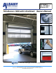
PN: 001451 Rev. 9/27/2010 Version 4.20 UltraSecure 3000 with UltraSmart Owners Manual Doors are UltraRugged, UltraReliable, UltraAffordable. Albany Door Systems - A Company of Albany International Corp. All Rights Reserved 1080 Maritime Drive, Port Washington, WI 53074 - 975-A Old Norcross Road, Lawrenceville, Georgia 30046 262-268-9885 www.albanydoors.
STATEMENT OF WARRANTY UltraSecure 3000 High Speed Doors ONE-YEAR WARRANTY ON MECHANICAL AND ELECTRICAL COMPONENTS Albany Door Systems warrants to the original owner of the door that the mechanical and electrical components will be free from defects in material and workmanship for a period of one (1) year from the date of shipment. The warranty does not cover fuses, heat lamp elements, bulbs, and seals.
High Speed Doors Operation TABLE OF CONTENTS Introduction 3 Product Description 4 Drawings 7 Inspection Plan 9 Safety Instructions 12 Troubleshooting 14 Maintenance 15 UltraSmart Control 17 Wiring 25 Wireless Safety System 31 UltraSmart Startup Procedure 32 Parts Diagram 37 ALBANY DOOR SYSTEMS CONTACT INFORMATION: Port Washington, WI 1080 Maritime Drive, Port Washington, WI 53074 Phone: 262-268-9885 Fax: 262-268-9895 Technical Support: 262-268-9885 www.albanydoors.
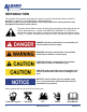
INTRODUCTION The contents of this manual are designed to help you operate and maintain Albany UltraLite™, UltraFast™, UltraCool™, and UltraFreeze™ high speed doors. DO NOT operate or perform maintenance on the high speed door unless you have read through the instructions in this manual. The safety alert symbol is used to identify safety information about hazards that can result in personal injury.
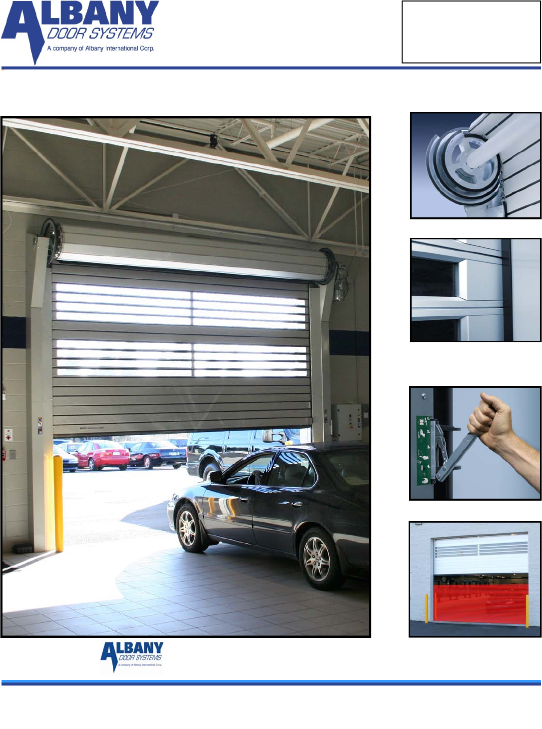
High Speed Doors Operation Product Description Principle The UltraSecure 3000 is a vertically opening high-speed rolling metal door primarily for external use. The door panel is made of aluminum slats connected to a special belt. The slats wind on up to three variable sized disc modules. They do not stack or wind onto each other, which protects the slats from excessive wear and produces smooth, contact-free frictionless operation that allows for the high opening speed.
Control Unit The UltraSecure 3000 is operated by a frequency converter control unit, which enables smooth acceleration and deceleration of the door. The maximum opening speed is 80 in/sec depending on door size. The door’s closing speed is approximately 24 in/sec. Manual Operation During maintenance work, or in the event of a power outage, the door may be opened manually by releasing the brake via the side column mounted egress lever.
Mechanical Safety Devices High Speed Doors Operation Springs are situated in separate chambers serving as a weight balancing system. The springs are enclosed and protected by metal covers. The door has a multi independent weight balancing system. Disengagement of the drive unit brake will not lead to a sudden drop of the door panel. For doors with a height less than 8 feet a top roll cover is absolutely necessary according to valid regulations.
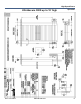
UltraSecure 3000 10’ high up to 16’ high 7 Manual #001451 Version 4.
UltraSecure 3000 up to 10’ high Rev.
Inspection Plan Observe the safety notices within the operation manual. Power to the door must be shut off prior to inspection of any door component. Installation fixings Before checking the following mentioned components the cover in front of the spring housing and eventually the existing top roll and motor cover must be dismantled. Drive unit Check retainer of the torque support and buffer. Check function of brake release lever.
High Speed Doors Operation Safety Instructions Area of Application and Classified Use Unless explicitly described otherwise, Albany Door Systems’ doors are developed and tested for use under normal operating conditions. For an application with special conditions (for example; onesided permanent load with temperatures, excessive pressure or special environmental conditions, etc.) contact Albany Door Systems. The door is defined primarily for use in industrial buildings.
General Safety Advice Please read the user manual carefully and keep it easily accessible for future use. Always follow the safety instructions mentioned in the user manual. Do not use this door for purposes it is not intended for. This user manual must also be transferred upon the transfer of this door to third parties. The use of the emergency lever may lead to a partial self-opening or closing of the door.
High Speed Doors Operation Troubleshooting To avoid damage to the door or injury to personnel during repair of malfunctions or errors, the following instructions should be carefully observed: Only trained personnel should accomplish Work. Turn off the power at the main switch prior to performing any work. Secure the main switch against being turned on again by locking it or by having a second person present. Secure the door’s operating area. Read "Safety Instructions".
Electrical Malfunctions For repair of electrical malfunctions see the error code manual at the appendix of the user manual instructions. Malfunction Possible Causes Door not functioning Door does not close Door closes only with next impulse Necessary Measures Power supply is off Check power supply and fuse Safety device damaged Check control unit and replace the fuse Main switch off Turn (main switch) switch on Stop-circuit interrupted Check stop circuit.
High Speed Doors Operation Inspection and Maintenance Maintenance and inspection work must only be performed by manufacturer trained authorized personnel. Before beginning the above-mentioned work the power must be disconnected by turning off the main power switch and locking it. The control unit must be checked to determine there is no power to it with the appropriate device. All ladders, scaffoldings, or similarly used equipment should correspond with valid safety regulations.
UltraSmart Control Panel Controls This key pad opens the door at a slower speed than normal door operation. The door will open as long as the key pad is pushed. This key pad closes the door at a slower speed than normal door operation. The door will close as long as the key pad is pushed. This key pad sets the time delay of the door closing once it has reached the selected open position in manual mode.
High Speed Doors Operation Control Panel Display The display on the front of the control panel shows two lines of information. The top line displays system status and the second line displays details of the function or specifics of errors. Normal Operation During startup the display will show the software version programmed into the control panel and whether or not the door is ready for normal operation.
Line One (1) Text Line Two (2) Text Startup: R-Bac Industries Door Not Ready Normal Operation: Door ready Opening: Opening — Full Opening — Part Open: Delay Timer Active Auto1 Close Delay Auto2 Close Delay Man1 Close Delay Man2 Close Delay DTC Timer Open Commanded :Delay Timer Active: DTO Timer (Display shown during a count - down of the timer.) Closing: Closing Normal: Warning Door Ready Startup: Version n.m Normal Operation: 0000000 The zeros indicate the number of door operations.
High Speed Doors Operation Adjustments Door Limit Adjustments Door limit adjustments are used to set four heights that the door opens and closes to. There are four (4) heights that the operator can set; Closed Limit, Full Open Limit, Partial Open Limit, and Break Away Reset Limit. The Closed Limit should always be checked for correct height or set before the other limits are set. When any limit is set all of the limits should be checked or set.
Periodic Maintenance Continued… Quarterly Inspection 1. Perform daily inspection. 2. Check all mounting hardware and verify that all nuts and bolts are tight. Hardware includes: wall anchors, cover hardware, motor mounting hardware, and bearing bolt nuts. 3. Check the break away function by performing the following steps: Stop the door so the bottom rail is between waist and chest high. Push the bottom bar out of one of the side columns.
High Speed Doors Operation Trouble Shooting Continued... DISPLAY OR DOOR Problem Possible Cause Corrective Action Door does not close. Held open by safety input or ac- Check display readout. Check tivator input. for lit LED on modules A and B. Remove corresponding wire on module A. For lit LED-if door closes: faulty activator. If LED stays lit and door stays open: faulty module. Held open if loop installed. Check loop module for lit LED. Remove loop wires from module terminal strip.
Trouble Shooting Continued... Light Curtain Problem Possible Cause Corrective Action Red alarm LED on. Transmitter disabled no synchronization signal. Check power supply and cable green LED should be on at all times. Yellow LED flashing. Sever electrical interference. Remove cables from high voltage. High ambient light. Check and adjust alignment of transmitter and receiver. Yellow LED always off. Receiver cannot see transmitter. Remove obstruction. No green LED.
High Speed Doors Operation Trouble Shooting Continued... Motor Drive Fault Problem Possible Cause Corrective Action Motor Drive Fault F38 phase U to ground. F39 phase V to ground. Check wiring between drive and motor. Check motor grounded phase. Contact manufacturer. F40 phase W to ground. F41 phase UV short. F42 phase UW short. F43 phase VW short. F70 power unit. Rev. 9/27/2009 Manual #001451 Check the motor and drive output terminal wiring for shorted condition. Contact manufacturer.
WIRE STRIP GAUGE MOTOR WIRING ¼” 8" 6" ¾” MOTOR WIRE CONDUIT BRAKE WIRES DRILL ONLY INTO BOTTOM OF BOX USE MINIMUM ¾” CONDUIT ¼” T2 MG T1 SEPARATE FOIL SHIELD MG SEPARATE FOIL SHIELD 6" T3 B1 MG B2 NOTE: MOTOR WIRES TO CHANGE DIRECTION OF MOTOR ROTATION – SWITCH T1 AND T2 ENCODER WIRING WIRE STRIP GAUGE ¼” ¾” LOW VOLTAGE CONDUIT ENCODER, SAFETY, ACTIVATION 4" DRILL ONLY INTO BOTTOM OF BOX USE MINIMUM ¾” CONDUIT TB2 TB3 TB1 TB1 TB4 23 Manual #001451 Version 4.
High Speed Doors Operation ACTIVATION WIRING N TOP 3 TERMINALS H NEXT 5 TERMINALS MANUAL ACTIVATORS MODULE - A TB2 1 2 3 4 5 CONNECT AS “NORMALLY OPEN” 6 H MODULE - A TB3 HERKULES™ MOTION SENSOR H BROWN GREEN N WHITE PINK Connect GRAY for Person Detection 1 2 3 4 5 6 GRAY RED Connect RED for Vehicle Detection MODULE - A TB3 FALCON™ MOTION SENSOR 1 2 3 4 5 6 GREEN RED H WHITE N BLACK REMOTE CONTROL H H N MODULE - A TB2 1 GRAY 2 3 4 5 6 GRAY RED BLACK TB3 1
25 Manual #001451 Version 4.
High Speed Doors Operation Rev.
27 Manual #001451 Version 4.
High Speed Doors Operation Rev.
ENABLING THE WIRELESS SAFETY SYSTEM If the door is equipped with Albany’s Wireless Safety System (indicated by the lack of a coil cord), the following steps must be taken to initialize the communications: 1. 2. 3. 4. 5. 6. Locate the RF transceiver on the bottom slat (shown to left) Remove the cover and locate the RFID number on the pull strip. Setup the UltraSmart™ Controller according to the procedure below: Hold the circuit board with one hand and pull out the strip. Replace the cover and 4 screws.
High Speed Doors Operation UltraSmart™ STARTUP PROCEDURE Albany’s UltraSmart™ control system is designed to accommodate numerous option modules and future technological advances. This manual will address necessary settings for the standard options; however, optional modules and special applications may require additional steps to be taken for proper setup. Refer to the control schematic shipped inside the panel enclosure for additional electrical and setup details.
The Open and Partial Limits are all relative to the Closed Limit. If the Closed Limit is reset to a different position, all other limit settings will change relative to the new Closed Limit setting. SETTING SYSTEM OPTIONS 1) Press and hold 2) Press Use until ―LIMIT SETUP‖ is shown on the display; Press until ―SYSTEM OPTIONS‖ is shown; Press and/or to cycle through the available options; Press and/or to change the value; Press to edit that option.
High Speed Doors Operation Instructions for Using Over-Travel Brake System. About the Over-Travel Brake System Your UltraSecure door is fitted with an over-travel brake system to stop your door in a controlled manner in the event a condition should arise leading to the door traveling past its upper limits. The system terminates the open command and immediately engages the gear motor brake.
Resetting the Brake To reset the brake, first loosen the clamp screws (Fig 3) so that you can move the yoke up and down easily. Clamp Fig 3. Move the yoke to the bottom of the clamp and retighten clamp Fig 4. Yoke at bottom position. Rotate yoke rest to a horizontal position and snap yoke into pocket. Reset door limits. Your door is now ready to go back into service. 33 Manual #001451 Version 4.
High Speed Doors Operation Electrical Operation Instructions When the over-travel mechanism has been engaged, the power to the control system will be disabled. The following procedure will reset the electrical system: 1. Turn the power off (wait 20 seconds) and then back on using the main panel disconnect switch. 2. With the power on, open the control panel and locate the over-travel sensor relay (shown here with teal override button). 3.
35 Manual #001451 Version 4.
High Speed Doors Operation Rev.
37 Manual #001451 Version 4.
High Speed Doors Operation Rev.
39 Manual #001451 Version 4.
High Speed Doors Operation Rev.
41 Manual #001451 Version 4.
High Speed Doors Operation Rev.
1080 Maritime Drive, Port Washington, WI 53074 Phone: (262) 268-9885 Fax: (262) 268-9895 albanydoors.