
Installation manual

24 031-171-C0-003 Rev. C
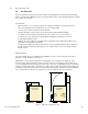
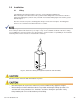
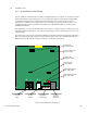
Enclosure Footprint
2
f
e
e
t
(
m
i
n
)
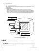
Connection made with Burndy connector
(P/N YGHR58C2W-3 or
equivalent)
Connection made with Burndy connector
(P/N YGHP58C2W-2TN or
equivalent)
Terminate at service
entrance ground
#2 AWG
Terminate at enclosure ground
Two (2) 8' ground rods,
6' apart minimum.
#6 AWG
2.0 Site Preparation, cont.
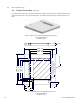
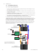
2.6 Enclosure Grounding
Alpha provides the following grounding method as a suggestion for sites not equipped with accessible
grounding facilities.
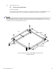
Grounding Specifications
• Configure enclosure footprint to accommodate swing arc of enclosure door. See Fig. 2-1.
• 1/2" x 8' copper ground rod, four places, driven about 2 feet (typical) from the corners of the pad.
• #6 bare copper wire loop terminated to each ground rod and buried a minimum of 30 inches below
grade. Use only corrosion-proof connections (25+ year life-span) and hardware suitable for direct
burial.
• #2 bare copper wire from loop to the enclosure.
The grounding method for a particular site depends upon soil type, available space, local codes, NEC (National
Electric Code), and other site-specific characteristics.
It is the responsibility of the installer to meet the requirements of all applicable national and local codes. Alpha
Technologies assumes no responsibility or liability for failure of the installer to comply with the requirements of
all applicable local and national codes.
Fig. 2-5, Suggested Grounding Method