
Installation manual

031-171-C0-003 Rev. C 19
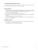
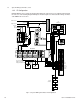
POS NEG
20A
48VDC Input
24VDC Output
Enclosure Ground
24VDC Breaker Panel
Front and Rear
Tamper Switches
31-32 Tamper
27-28 Converter Fail
Air Conditioner
DC-DC Converter
Customer Supplied
-48VDC Positive Ground
-48VDC Input Bus
Alarm
Terminal
47-48 Cooling System Major
Alarm
49-50 Cooling System Minor Alarm
5A
10A
Red
Red
Red
Red
Black
Black
Black
Site Ground
(Customer Installed)
(-)
(+)
(+)(-)
(-)
(+)
Heater
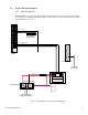
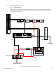
1.3 System Wiring Schematics, cont.
1.3.3 ‘C’ Configuration
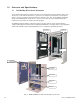
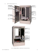
Radium MiniBays arrive at their destination with all internal components preassembled and installed in
the enclosure. The following diagram will help the installer/engineer to understand the wiring schematic
of the RMB-E-911 enclosures.
Fig. 1-5, System Wiring Schematic ‘C’ Configuration