
Installation manual

18 031-171-C0-003 Rev. C
1.3 System Wiring Schematics, cont.
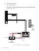
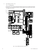
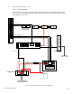
1.3.2 ‘B’ Configuration
Radium MiniBays arrive at their destination with all internal components preassembled and installed in
the enclosure. The following diagram will help the installer/engineer to understand the wiring schematic
of the RMB-E-911 enclosures.
Fig. 1-4, System Wiring Schematic ‘B’ Configuration
Breaker Box
Ground Bar
RSM Module RSM Module RSM Module RSM Module
25
24
23
22
21
20
19
18
17
16
POS
POS
NEG
NEG
12VDC 12VDC
Neutral
Line 1
Line 2
Utility Ground
Earth Ground
Enclosure
Ground Bar
(-)
Air
Conditioner
Battery
Compartment
Fan
Tamper
Swirches
Alarm Patch
Panel
Tamper
AC Fail
Rect. Major
Rect. Minor
HVA
LVA
Fuse/Breaker
Battery fan Fail
Cooling Major
Cooling Minor
24VDC
24VDC
24VDC
120VAC
120VAC
Battery
heater
Enclosure
heater
Temp Sensors
Rectifier
(-)(+)
See Fuse installation
detail in Section 3.6,
Battery Installation