
Instruction manual
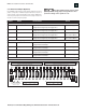
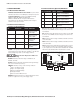

LED DESCRIPTION COLOR CONDITIONS
AC ON (D19) AC Power Green Lights when AC
voltage is present
on the input
DC OUT (D15) DC Output Green Lights when DC
voltage is present
on the output
AC FLT (D22) AC Fault Yellow Lights when AC
voltage is low
or missing
COM FLT (D16) Common Fault Yellow
See COM FLT below
GND FLT (D23) Earth Ground Fault Yellow Lights under an
earth ground fault
condition
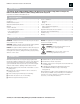
AC ON: for safety reasons this LED illuminates any time there
is AC voltage present at the AC input, regardless of the AC fault
status, battery charge state or power supply condition.
Always check for AC presence with a volt
meter before servicing.
DC OUT: illuminates when DC voltage is available at the
DC+/DC- terminals.
AC FLT: illuminates when AC voltage falls below approximately
85% of the nominal input setting.
COM FLT: illuminates on any of the following conditions:
High or low battery voltage
High or low output voltage
Missing or damaged battery
Earth ground fault
Fault recieved on ABC Connector
GND FLT: illuminates when there is a ground fault between either
positive or negative rail of the power supply output.
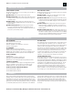
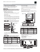
B1: Illuminates when AC voltage is present on Buss 1of the ABC
Connector. In the RMDC series this voltage is sourced from the
PS5-M board
B2: illuminates when AC voltage is present on Buss 2 of the ABC
Connector. In the RMDC series this voltage is sourced from the
PS5-M board
DC1: illuminates when voltage is available at the DC1 terminals
of the FAI module.
DC2: illuminates when voltage is available at the DC2 terminals
of the FAI module.
FAI: illuminates when a valid FAI input signal has been received
on the FAI input terminals of the FAI module. When this LED is
lit, the output power of the FAI module is disabled. DC1 and DC2
LEDs will not be illuminated when the FAI input is received.
LED DESCRIPTION COLOR CONDITIONS
B1 Buss 1 Voltage Green Lights when voltage is present
on Buss 1 of the ABC buss
B2 Buss 2 Voltage Green Lights when voltage is present
on Buss 2 of the ABC buss
DC1 DC1 Voltage Green Lights when voltage is available on
the DC1 output terminals
DC2 DC2 Voltage Green Lights when voltage is available on
the DC2 output terminals
FAI FAI Input Red Lights when a valid FAI input
is received
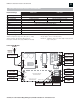
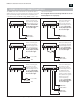
3.2.3 Indicators On the (Optional) FAIM Board
9
AlarmSaf, Inc. 65A Industrial Way, Wilmington, MA 01887 978-658-6717 www.alarmsaf.com
RMDC Series Installation Instructions 52-376 Rev B01
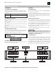
3.2 VISUAL INDICATORS
3.2.1 External Visual Indicators
Illuminated Circuit Breaker/Power Switch: the power switch
illuminates red when it is in the ON position and power is present.
Front Panel Indicators: all units except RMDC-PS5-M-UL,
RMDC-PS5-M-UL-FAI, RMDC-PS5-MD-UL and
RMDC-PS5-MD-UL-FAI have front panel LED indicators.
Each output has one LED which illuminates when voltage is
available at that output terminal.
3.2.2 Internal Visual Indicators
Indicators on the PS5-M board
1510
F1
ATM -10
1010
REPLACE FUSES ONLY WITH SAME STYLE AND RATING
UTILISER UN FUSIBLE DE RECHANGE DE MEME
B2
B2
B1
B1
FAI
FLT
RET
P2
B1 B2
FAI
FAI
MODE
TB1
FAIM
AlarmSaf © 2006
D1 D2
P1
TB2
D13 D12
DC1 DC2
D10
J1
J3
J2
BUSS 2
CONNECT
38-137 REV B01
+– –+
V– A B V+ L
+DC1– –DC2+
FAI INPUT PWR LTD
DC1
DC 2