
Instruction manual

AlarmSaf, Inc. 65A Industrial Way, Wilmington, MA 01887 978-658-6717 www.alarmsaf.com
7
RMDC Series Installation Instructions 52-376 Rev B01
3.1 JUMPER AND SWITCH CONFIGURATION
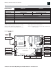
3.1.1 Internal Jumper and Switch Configuration
To access the internal boards, remove the top cover.
Before powering the system, the jumpers on
the internal board(s) must be set for proper operation. Do not
change jumper or switch settings while the unit is powered
or damage to the system can occur.
PS5-M Jumper and Switch Settings
Each unit contains either one or two PS5-M boards. The voltage
switch and jumpers on each board need to be configured for
desired operation.
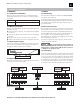
Output Voltage Setting
Before installing an RMDC system, the output voltage setting
switch of the PS5-M board(s) must be set. Set the switch toward
the green AC visual indicator for 12V, away from the green AC
visual indicator for 24V. (The PC board is labeled with the voltage
settings.) If the RMDC contains two PS5-M boards, they may be
set for two different voltages or the same voltage.
Do not change the switch setting while
the unit is powered or damage to the system can occur.
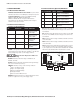
AC VISUAL INDICATOR
EARTH GROUND
OPTION JUMPER
BATTERY PRESENCE
OPTION JUMPER
OUTPUT VOLTAGE
SELECT SWITCH
EARTH GRND
DETECT
BAT
DETECT
VOLTAGE
SELECT
AC ON
12V
24V
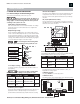
JUMPER DESCRIPTION SETTINGS DEFAULT
J1 FAI Latch Left - Latching Right
Right - Non Latching
J2 ABC Buss
Up Up
Connect
J3 FAI Buss
Down Down
Connect
JP6 JP5 JP7
JP4 ABC
COM
FLT
AC
FLT
GRND
FLT
NO NC C NO NC C
AC FLT COM FLT
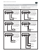
JP5 & JP7 CONNECT
TO BUSS 1 OF
THE ABC CONNECTOR
JP5 & JP6 CONNECT
TO BUSS 2 OF
THE ABC CONNECTOR
3.1.1.3 Jumper Settings
For proper operation, the jumpers on the PS5-M should be set
appropriately.
Do not change the jumper settings while
the unit is powered or damage to the system can occur.
JP9 Earth Ground Option
This jumper allows disabling of the earth ground fault detection
for applications that either do not require earth ground fault
detection or where earth ground fault detection is provided by
the panel.
JP5, JP6, JP7 (ABC Connector Buss)
This fuse determines how the output of the PS5-M connects to
the ABC Connector. For all RMDC units the ABC Buss Select Fuse
should be connected to J5 and J7.
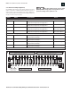
3.1.2 FAI Module Jumper Settings (Optional)
If the RMDC has FAI capability, the jumpers on the Fire Alarm Interface
Module (FAIM) need to be set for proper operation.
J1 FAI Latch
For applications that require the FAI activation to latch, see
Appendix A for wiring options
J2 ABC Buss Connect
This jumper MUST be set in the up position
J3 FAI Buss Connect
This jumper has no effect and should be set in the down position.
JP10 Battery Presence Option
This jumper allows disabling of the battery presence detection for
applications where no backup battery set is used. Jumper is
provided without a default setting. Installer must select setting.
1510
F1
ATM -10
1015
REPLACE FUSES ONLY WITH SAME STYLE AND RATING
UTILISER UN FUSIBLE DE RECHANGE DE MEME
B2
B2
B1
B1
FAI
FLT
RET
P2
B1 B2
FAI
FAI
MODE
TB1
FAIM
AlarmSaf © 2006
D1 D2
P1
TB2
D13 D12
DC1 DC2
D10
J1
J3
J2
BUSS 2
CONNECT
38-137 REV B01
+– –+
V– A B V+ L
+DC1– –DC2+
FAI INPUT PWR LTD
DC1
DC 2
SECTION 3: OPERATION
JUMPER DESCRIPTION SETTINGS DEFAULT
JP10 Bat Presence Jumper On - Enable None
(Bat Detect) Fault Detection Jumper Off - Disable
JP9 (Earth Earth Ground Jumper On - Enable Enable
(Ground Detect) Fault Detection Jumper Off - Disable
JP5, JP6, JP7, ABC Buss N/A Buss 1
(Buss 1 / Buss 2) Select (JP5 & 7)