
Instruction manual

2.2 WIRING
2.2.1 Wire Routing
All wiring must be installed in accordance with NFPA70 (NEC760)
and all local code requirements.
Power limited wiring requires that power limited and non-power
limited wiring remain physically separated. All power limited circuits
must remain at least one-quarter inch (1/4”) away from any non-
power limited wiring.
2.2.2 AC Power Connection
Before using the power outputs, the unit must be connected to the
main electrical power. Use the supplied cord set to connect the unit
to a live AC outlet and verify that the AC indicator light built into
the main ON/OFF switch on the rear panel is illuminated when the
unit is turned on. The unit may have a delayed power up of
approximately five seconds due to internal diagnostic processes when
there is no battery set connected.
Shut off the electrical power to the location of the unit and then
complete the general installation.
Before powering the system, the jumpers on
the internal board(s) must be set for proper operation. Do not
change jumper or switch settings while the unit is powered
or damage to the system can occur.
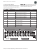
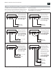
2.2.3 Field Wiring
Locate the terminal wiring blocks on the back panel of the unit and
remove the terminal block from the header. (There are two locking
screws, one on either end of the terminal block.) Connect the wiring
for the equipment to be powered, battery set, fault outputs, etc. to
the terminal block. The back panel of the enclosure is labeled with
the terminal and polarity indications (see also section 1.2). Replace
the terminal block on the header and tighten the locking screws.
AlarmSaf, Inc. 65A Industrial Way, Wilmington, MA 01887 978-658-6717 www.alarmsaf.com
6
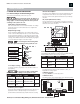
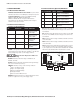
2.1 MOUNTING
2.1.1 Temperature and Humidity
Mount the unit in locations that meet the following temperature
and humidity requirements. Do not expose to conditions outside of
these ranges.
RMDC Series Installation Instructions 52-376 Rev B01
2.1.2 Mounting in the Rack
Mount the unit in a standard 19” equipment rack using the appropriate
hardware for the rack.
Ensure all jumpers, switches, etc. are set properly before installing
into the rack.
Locate an open 2RU slot in the rack and remove the filler panel(s),
if present.
Slide the unit into the open slot from the front of the rack.
Install the four mounting screws into the end brackets of the unit.
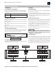
2.1.3 Removing the Faceplate
To remove the faceplate of the RMDC unit, remove the four screws
at the corners of the faceplate. Pull out gently on the faceplate to
disengage the LEDs from the holes in the faceplate.
2.1.4 Replacing the Faceplate
Gently slide the faceplate over the output LEDs and secure with the
four screws removed from the faceplate.
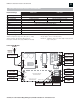
Model Shown:
RMDC-PS5-MD-16F-UL-FAI
Power Supply Unit 1
NO NC C
AC
FAULT
NO NC C
COMMON
FAULT
– +
BAT
– +
SYS
DC
– +
FAI
DC
L V+ B A+
FAI INPUT
OUT 8
– +
OUT 7
– +
OUT 6
– +
OUT 5
– +
OUT 4
– +
OUT 3
– +
OUT 2
– +
OUT 1
– +
OUT 16
– +
OUT 15
– +
OUT 14
– +
OUT 13
– +
OUT 12
– +
OUT 11
– +
OUT 10
– +
OUT 9
– +
Power Supply Unit 2
NO NC C
AC
FAULT
NO NC C
COMMON
FAULT
– +
BAT
– +
SYS
DC
– +
FAI
DC
L V+ B A+
FAI INPUT
OFF
RESET
ON
RESET
OFF
AC POWER
AC INPUT OUTPUTS 1 – 8OUTPUTS 9 –16
MAIN POWER SWITCH
& CIRCUIT BREAKER
MAIN DC OUTPUT
FAI OUTPUT
FAI INPUT
FAULT OUTPUT
RELAY CONTACTS
POWER SUPPLY 2
BATTERY CHARGE
MAIN DC OUTPUT
FAI OUTPUT
FAI INPUT
FAULT OUTPUT
RELAY CONTACTS
POWER SUPPLY 1
BATTERY CHARGE
REMOVE (REPLACE) FOUR SCREWS
1 2 3 4 5 6 7 8 9 10 11 12 13 14 15 16
Temperature 0°C to 49°C (32° to 120°F)
Humidity 32°C (90°F) @ 93%
SECTION 2: INSTALLATION