
Instruction manual

5
AlarmSaf, Inc. 65A Industrial Way, Wilmington, MA 01887 978-658-6717 www.alarmsaf.com
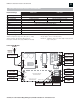
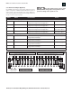
1.2 TERMINAL DESCRIPTIONS
The terminal strips are located on the back panel of the unit. All
terminal strips are removable with locking screws and accept wire
sizes from 14-26AWG. Wire should be sized appropriately for voltage
drop and current carrying capability. All terminals are labeled for
polarity where appropriate.
1.2.1 AC Input
120VAC input: 3-wire line cord set included with unit.
1.2.2 DC Distributed Outputs (OUT 1 - OUT 8/16)
Each distributed output is individually over-current protected (3A
for fuse protected units, 1.6A for PTC protected units). In dual-
supply models, each output can be programmed for either supply
by front panel jumpers.
These distributed outputs are not present in models
RMDC-PS5-M-UL, RMDC-PS5-M-UL-FAI, RMDC-PS5-MD-UL
and RMDC-PS5-MD-UL-FAI
1.2.3 Battery Terminals (BAT +/–)
Terminals are internally fused at 15A.
Battery presence detection is available by setting internal jumpers.
Each internal supply has one set of battery terminals.
Minimum battery charging capacity: 7Ah.
Maximum battery charging capacity: 80Ah within 48 hours.
When no batteries are connected there is no voltage on the
battery terminals. The battery charger does not enable until it
senses a battery on the terminals.
Note: It is the responsibility of the installer to determine the minimum
battery requirement for the specific application in which the supply
is being used. Backup batteries should be serviced at regular intervals
as determined by local and/or national codes.
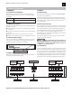
AlarmSaf offers an RMBE Battery Enclosure for use with the
RMDC series power supplies. It provides battery backup in
a standard 19 inch 2RU rack mountable enclosure. The RMBE
includes 4 12V-7Ah batteries and can be configured for
single or dual output. Each output can be configured for
either 12 or 24VDC by pluggable jumpers on its back panel.
Each battery in the enclosure is protected from overcurrent,
short circuit and incorrect configuration by a 9A PTC.
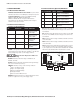
Model No. RMBE-1224-4B7
1.2.4 Bulk Output Terminals (SYSTEM DC +/–)
Bulk output of internal supply. Full current capacity of supply is
available on this single output terminal set.
Each internal supply in the enclosure has one bulk output.
1.2.5 Fault Outputs (AC FAULT / COMMON FAULT)
Form C contacts.
Contacts rated 1A @ 24VDC, 0.5A @ 120VAC
Fault relays employ “fail-safe” operation and are powered in a
non-fault condition (connection between common and NO when
no fault exists).
Each internal supply has independent sets of fault contacts.
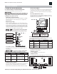
1.2.6 FAI Input / FAI DC (Optional)
The FAI function is optional and must be requested at time of order.
The FAI DC +/– terminals are a bulk output controlled by the
FAI input terminals. The full current of the supply is available
at this output.
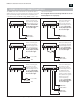
The FAI input terminals are the control input for the FAI
function. Terminal usage is as follows:
A This terminal is the positive input terminal. It accepts a voltage
from a minimum of 9VDC to a maximum of 30VDC supplies
from either an internal or external source for activation of
the FAI function.
B This terminal serves one of two functions, depending on the
internal jumper settings.
When FAI input is configured as a non-latching input,
this terminal is the common input terminal. It accepts
a dry contact or open collector connection switched
to DC common.
When FAI input is configured as a latching input,
this terminal is tied to the FAI input L terminal through
a normally closed contact or manual switch. When the
FAI input is activated, this terminal latches the input on.
Opening the normally closed contact resets the FAI input.
V+This terminal provides a current-limited DC voltage to
be used with an external dry contact to activate the
positive input.
L This terminal provides a voltage output to be used with
the B terminal and a remote manual switch for latching the
FAI condition until manually reset.
NOTE: In certain applications, one of the RMDC DC– terminals
must be used in conjunction with the FAI wiring to provide a
common system negative connection.
See Page 10, Appendix A for FAI connection examples.
1.3 FUSES
When replacing fuses in the RMDC, use only the equivalent type and
rating. The RMDC utilizes commonly available Automotive Miniature
fuses (type ATM). Units whose model numbers end in an “F” employ
ATM-3 fuses on the PCB located behind the front panel of the RMDC.
A spare fuse is provided on the bottom right corner of the PCB.
Each internal PS5-M contains two replaceable fuses: the Battery Fuse
and the ABC Buss Fuse. Both fuses are rated at 15A (ATM-15). The
AC input fuse is soldered-in and non-replaceable. If it is determined
that this fuse has opened, the PS5-M board must be returned to
AlarmSaf for repair.
RMDC Series Installation Instructions 52-376 Rev B01