
Installation Guide

3
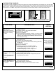
2. Reed selection jumper W1 is located in the center of the
PCB. The jumper should be set to the side of the unit that
will have the magnet installed. (See Figure 5 below).
3. Select jumper options (J1- J9) as follows. (Refer to the
Jumper Options table, below and page 5).
Important: The jumpers are only read at startup and when-
ever the unit is armed. If the jumpers are changed after power
up, the unit must be rearmed before the jumper changes take
effect. In addition, the unit will not function unless Tamper
Screw (SC543) is in place.
J1: Siren. Factory default sound is a Sweeping Siren.
Jumper moved to the "lower" position (near the edge of
the circuit board) produces a Steady-Tone Siren.
J2: Pulsing Siren. Default setting is Constant-ON.
Jumper moved to the "lower" position produces a siren
that "pulses" on and off.
J3: Siren 2-Minute Timeout. Default setting (jumper at
"upper" position) enables the timeout, allowing the si-
ren to turn off two minutes after the alarm is tripped--if
door is closed within that two minute period. Jumper
moved to the "lower" position disables the timeout,
keeping the siren on until manually reset. To indicate
that an alarm has occurred (Alarm Memory), the LED
will start flashing. Alarm Memory is cleared after
approximately 4 hours or by rotating the lock cylinder
counter-clockwise and removing the key. Note: If the
door is still open after two minutes, the alarm will
restart.
J4: Security Level. Default setting (jumper at "upper" po-
sition--High Security) enables a latching alarm when
tripped--siren remains on for 2 minutes or until turned
off by the key (turn key to the left). Jumper moved to
the "lower" position will set the lower security non-
latching "Door Ajar" alarm mode--siren turns on when
door is open, and turns off (and resets) when door is
closed.
Jumpers 5-7: These jumpers are used for doors that are in-
tended for authorized entry and exit, providing an "Arming/Exit"
delay time when exiting, and an "Alarm/Entry" delay time when
entering. Disarming with the key within the programmed time
will prevent an alarm. See descriptions for J5 and J6 below for
specific examples. Note: If jumpers J6 and J7 are both moved
to the "lower" position, the result is a delay of 2 minutes.
J5: Arming/Exit Delay. Default (jumper at "upper" posi-
tion) provides no Arming/Exit Delay. Jumper moved to
the "lower" position enables a fixed 15-second
"Arming/Exit Delay", allowing exit without alarm (i.e.
the time between turning the key to the left and when
the system actually arms). For example, if J5 is at the
"lower" position, the protected door can be used as an
"exit door"---first, insert and turn metal key to the left,
then open door, exit, and let the door close. When the
delay expires, the PG21 re-arms.
J6: Alarm/Entry Delay. Default (jumper at "upper" posi-
tion) provides no delay. Jumper moved to the "lower"
position (near the edge of the circuit board) provides
15 seconds of Arming Delay time. If jumpers J6 and
J7 are both enabled, the result is an Alarm Delay of 2
minutes. For example, if J6 is at the "lower" position,
the protected door can be used as an "entry door"---
first, open the door from the outside, insert and turn
metal key to the left, and let the door close. When the
delay expires, the PG21 re-arms.
J7: Alarm/Entry Long Delay. Default (jumper at "upper"
position) provides no delay. Jumper moved to the
"lower" position selects 60 seconds of Arming Delay
time. If jumpers J6 and J7 are both moved to the
"lower" position, the result is an Alarm Delay of 2 min-
utes.
J8: Annunciator. The annunciator provides a 1 second
"beep" sound. The jumper in the factory default posi-
tion (jumper at "upper" position) disables the "beep".
Jumper moved to the "lower" position selects the
"beep" sound when the door is closed and unit is dis-
armed. Note: This jumper selection will operate only
if the PG21 is mechanically configured to "On/Off"
mode (see page 2, Section "C", "CONFIGURATION").
J9: Annunciator Volume. The jumper in the factory de-
fault position (jumper at "upper" position) produces a
low volume beep. Jumper moved to the "lower" posi-
tion (near the edge of the circuit board) produces a
high volume beep.
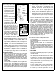
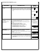
Jumper Number and De-
scription
Jumper Default Position
(Upper Position--see Figure 4)
Jumper Enabled Position
("Down" near edge of circuit board)
J1-Siren: Sweeping Steady
J2-Siren Pulsing: Disable Enable
J3-Siren 2-Minute Timeout: Enable Disable
J4-Security Level: High/Latching Low/Non-Latching
J5-Arming Delay: No Arming Delay 15 Seconds
J6-Alarm Delay 15 Sec.: Disabled Enabled*
J7-Alarm LongDelay 60 Sec.: Disabled Enabled*
J8-Annunciator (Beep): Disabled Enabled
J9-Annunciator Volume: Low Volume High Volume
*NOTE: If Jumpers 6 and 7 are both enabled, Alarm Delay = 2 minutes
Jumper Options
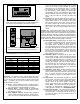
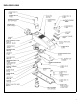
PCB
Fig 5. Reed selection jumper W1 found in the center of the PCB.
Jumper shown is configured to enable the right reed switch.
Jumper set
to right...
...enables right
reed switch
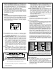
Fig 4. CLEAR Button and Jumpers.
(Jumpers shown in default ("up") positions).
1 2
3
4
5 6 7
8
9
Clear