
Installation Guide

2
7. Position the Magnetic Actuator as indicated by the red
sticker on the side of the Housing Cover. If stickers were
removed, use the Magnet Alignment Mode (see page 3) or
place the Magnetic Actuator 1½ " from the bottom edge of
the Baseplate. Mark holes and (as with the Baseplate)
use a 1/8" (0.125") bit, and drill the hole 1" deep.
8. Install the Magnetic Actuator with the supplied #8 sheet-
metal screws (1"). Be sure to insert the Magnet (P1358)
and Magnet Cover (P0291) into the Magnet Housing
(P0290) before mounting.
B. WIRING
External wiring to the PG21 requires that the unit be mounted
on the frame with the magnet on the adjacent door. (The
PG21 may be mounted on a door with the addition of a Model
271 Flexible Cable). All wiring is made at its terminal strip.
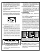
Wiring connections are summarized in the Wiring Diagram
shown below in Figure 1.
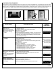
Relay (Terminals 1-3). Terminal 1 = Normally Closed;
Terminal 2 = Common; Terminal 3 = Normally Open.
On alarm, the relay will activate and remain latched for
as long as the sounder is on.
Reed Switch (Terminals 4 & 5). Connect external reed-
switch contacts to Terminals 4 and 5 and remove reed
selection jumper W1 located in the center of the PCB.
Note: If reed switches are wired in series as shown be-
low in Figure 2, several doors may be monitored
simultaneously. Using #22AWG wire, maximum wiring
distance should not exceed 50 feet. Note: When exter-
nal reed switches are used, the internal reed switches
must be disabled by removing the reed selection (W1)
jumper.
Power (Terminals 6 & 7). Connect an external power
supply: positive (+) red to Terminal 7; negative (-) black
to Terminal 6. Leave in the internal battery as a backup
battery. If using the Alarm Lock PP100 Power Supply,
connect the two battery clips to the unit and the internal
battery as labeled.
Doorbell (Terminal 8). Connect between terminal 8 and 6
using momentary-on switch to activate Doorbell. Pro-
duces alternating tone. Will not operate during Alarm or
during Arm delays. Note: Do not use a lighted door
bell button--the light will drain the battery.
Strobe Connector (Jumper 14). If using a Strobe unit, run
the wires through Strobe Assembly and Palnut and plug
female polarized connector into J14 located in the cen-
ter of the PC board (see Fig 5b, page 4). Note: J14
(Pin1) is the external Strobe Power (9 volts) and J14
(Pin2) is the Strobe Ground.
The Strobe and siren are on the same circuit, therefore
the timeout duration is the same for both.
C. CONFIGURATION
There are two configuration sections: Mechanical Con-
figuration and Jumper ("Software") Configuration.
Mechanical Configuration
You must decide if the PG21 lock will be kept in its original
factory configuration (in "Always Armed" mode) or con-
verted to a manual "On/Off" mode.
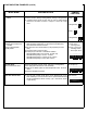
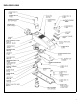
The PG21 is shipped from the factory with a Torsion Spring
(HW1149) installed (see Figure 7, page 7) which forces the
Cam Assembly (HW1187) against the PC Board switch, thus
keeping the lock Armed whenever the key is removed. If
you wish to convert the lock to On/Off mode, allowing the
Cam Assembly to be moved in either position, the Torsion
Spring must be disabled--disconnected from the Cam As-
sembly. To disable the Torsion Spring, use a small screw-
driver and unhook the end of the Torsion Spring from the
Cam Assembly, as illustrated in the following images: Note:
To allow for future re-conversion, the Torsion Spring can be
simply disconnected and not removed (see Fig. 3c below).
See the following three images (Figs. 3a-3c) to help you con-
vert your PG21 from "Always Armed" to "On/Off" mode, or to
restore your PG21 back to its original factory condition
("Always Armed").
Jumper Configuration
Before configuring the jumpers, also see page 5 and decide
which options should be selected for your application.
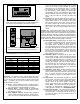
1. Connect the battery; a chirp will sound ensuring that
power is properly connected. Important: Press the small
CLEAR button at the lower-left corner of the circuit board
(see Figure 4 below).
NOTE: REMOVE "W1" JUMPER INSIDE HOUSING
(ONLY IF EXTERNAL REED SWITCHES ARE USED).
4
5
DOOR 1
DOOR 2 DOOR n
MAXIMUM WIRING DISTANCE = 50 FEET
USING #22AWG WIRE
Fig. 2. Multiple door monitoring (wired in series).
1
2
3 4 5 6 7 8
REED
SWITCH*
*ALSO SEE FIG 2
EXT.
POWER
12VDC
RELAY
NC NO
C
Fig 1. Wiring Diagram.
+
_
DOORBELL
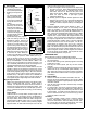
Figs. 3a-3c: Disconnect Torsion Spring from Cam Assembly:
Fig 3a displays the Torsion Spring as it is installed from the factory (thus
"Always Armed" mode). To convert to "On/Off" mode, first lift leg of the
Torsion Spring (Fig. 3b) from Backplate, then unhook other end of spring
from Cam, releasing tension (Fig. 3c), and allowing Cam to move freely.
Fig 3a Fig. 3b Fig. 3c
Cam
Assembly
Torsion
Spring
Lift leg of
spring...
...then
unhook
this end