
Programming instructions

11
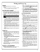
WIRING
See the Installation Manual for more information.
Batteries:
Use only 3.0 volt Lithium Type 123 batteries (or equiva-
lent). Two (2) batteries of this type are needed.
BATTERY REPLACEMENT
When a valid code is entered and the batteries are weak,
the red & green LED's will light and the sounder will sound
for 4 seconds. Replace with two (2) 3.0 volt Lithium Type
123 batteries. Always replace weak batteries as soon as
possible.
CAUTION: Do not press any keys while batteries are
disconnected or you may erase the real-time clock
settings.
1. Insert key in cylinder and turn counterclockwise to al-
low access to the battery compartment screw. With the
supplied 5/64" Allen wrench, loosen the battery cover
screw only until the battery cover is able to slide off.
2. Pull out the battery pack and quickly replace both
batteries - within 1 minute.
3. If you do not hear the 3 beeps when power is re-
applied, all programming and settings have been re-
tained, and the lock is ready for use. Go to step 5.
4. If you do hear 3 beeps when power is re-applied, do
not press any keys for 15 seconds. After the 15
second period, the LED will flash red 6 times and 6
beeps will sound. Reset the clock using functions 38, 39
and 40.
5. Slide the battery cover back in place and tighten the
screw.
POWER UP
• When applying power to the lock for the first time, stop
and follow the procedure outlined in "Quick Start, First
Time Start Up" on page 12.
• When power is re-applied to a lock that was already
operational, proceed as follows:
1. Disconnect battery pack connector.
2. With battery power disconnected, press and hold
down ; for 10 seconds to ensure discharge of all
capacitors.
3. Re-connect battery pack (lock will sound 3 short
beeps). If beeps are not heard, then restart at step 1.
4. Do not press any keys for 15 seconds.
5. After 15 seconds, the LED will flash red 6 times and 6
beeps will sound.
The lock is now ready for use. The pre-existing program is
loaded from fixed memory. Reset the clock using functions
38, 39 and 40 if necessary.
ERASE ALL PROGRAMMING
RESTORE FACTORY DEFAULT (original "out of box" set-
tings that were set at the factory will be loaded).
1. Enter the current Master Code (if not known, proceed
directly to ALTERNATIVE METHOD, below). Wait for
the green light and press ; until multiple beeps are
heard. You are now in Program Mode.
2. Press ; 99 ; 000 :.
3. Listen for 6 beeps. The lock will re-lock. All settings and
programming have been erased. Proceed directly to
page 12, Quick Start, and follow the procedure "Enter
Program Mode and Change Factory Master Code".
ALTERNATIVE METHOD
Note: This method requires the lock first be removed from
the door.
1. Insert key in cylinder and turn counterclockwise to al-
low access to the battery compartment screw. With the
supplied 5/64" Allen wrench, loosen the battery cover
screw only until the battery cover is able to slide off.
2. Disconnect the battery pack.
3. Remove the back plate by unscrewing the two Phillips
head screws. Note: Some models have four Phillips
head screws. Be careful not to damage the motor drive
wires.
4. Locate jumper header JP1 near the top of the printed
circuit board and install the jumper (provided) across pins
1 and 2 of JP1.
5. Press and hold down ; for 10 seconds (to ensure
all power is drained from the lock) and release.
6. Connect the batteries and--within 5 seconds--press
and hold ;. After hearing 6 additional beeps, re-
lease ;. If you do not hear these 6 additional
beeps, you must start over at step 2. Failure to follow
this exact procedure can result in erratic lock behavior.
7. Test by pressing the default Master Code of
123456 (a beep will sound
and the lock will unlock).
8. Remove the jumper from JP1 pins 1 and 2 and place
jumper on 1 pin for storage.
9. Carefully reinstall the back plate STRAIGHT onto the
lock body. Be careful not to pinch or damage the motor
drive wires. While inserting the back plate, be sure the
rear pin of the tailpiece inserts into the spindle hole--
check this alignment after installation by pushing on the
spring-loaded tailpiece to verify that it smoothly moves
up and down. Replace the two (or four) Phillips head
screws to secure the back plate. Note: It may be nec-
essary to tighten the battery screw previously loosened
in step 1.
10. Re-mount the lock on the door. With the battery
back inside its compartment, slide the battery cover
back in place and tighten the screw.
All settings and programming have been erased. Pro-
ceed directly to page 12, Quick Start, and follow the
procedure "Enter Program Mode and Change Fac-
tory Master Code".
Wiring and Power Up