04QX ® Loader Part No. F-3672 Published 1/02 OPERATOR’S MANUAL This Operator’s Manual is an integral part of the safe operation of this machine and must be maintained with the unit at all times. READ, UNDERSTAND, and FOLLOW the Safety and Operation Instructions contained in this manual before operating the equipment. RHINO® 1020 S. Sangamon Ave. Gibson City, IL 60936 800-446-5158 Email: parts@servis-rhino.com © 2002 Alamo Group Inc.
TO THE OWNER/OPERATOR/DEALER All implements with moving parts are potentially hazardous. There is no substitute for a cautious, safe-minded operator who recognizes the potential hazards and follows reasonable safety practices. The manufacturer has designed this implement to be used with all its safety equipment properly attached to minimize the chance of accidents. BEFORE YOU START!! Read the safety messages on the implement and shown in your manual.
TO THE OWNER/OPERATOR/DEALER All implements with moving parts are potentially hazardous. There is no substitute for a cautious, safe-minded operator who recognizes the potential hazards and follows reasonable safety practices. The manufacturer has designed this implement to be used with all its safety equipment properly attached to minimize the chance of accidents. BEFORE YOU START!! Read the safety messages on the implement and shown in your manual.
TABLE OF CONTENTS SAFETY SECTION . . . . . . . . . . . . . . . . . . . . . . . . . . . . . . . . . . . . . . . . . 1-1 Safety Precautions . . . . . Safety Hazard Signal Words Decal Locations . . . . . . Safety Decals. . . . . . . . . . . . . . . . . . . . . . . . . . . . . . . . . . . . . . . . . . . . . . . . . . . . . . . . . . . . . . . . . . . . . . . . . . . . . . . . . . . . . . . . . . . . . . . . . . . . . . . . . . . . . . . . . . . . . . . . . . . . . . . . . . . .
SAFETY SECTION Safety Section 1-1 .
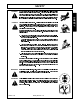
SAFETY SAFETY PRECAUTIONS A careful operator operates best. Most accidents can be SAFETY avoided by observing certain precautions. Read to help prevent accidents. Equipment should Stop loader arms gradually when lowering or lifting. 7. Use caution when handling loose or shiftable loads. 8. Carry bucket or attachment at a low position during transport 9. When for better visibility. all precautions that follow before operating your tractor and loader 6.
SAFETY PELIGRO! Si no lee Ingles, pida ayuda a alguien que si Io lea para que Ie traduzca las medidas de seguridad. SAFETY DANGER! Never operate the Power Unit or Implement until you have read and completely understand this Manual, the Power Unit Operators Manual, and each of the Safety Messages found in the Manual or on the Power Unit and Implement. Learn how to stop the Power Unit engine suddenly in an emergency.
SAFETY SAFETY DANGER! DANGER! Never allow children to operate or ride on the Power Unit or Implement. Do not mount the Power Unit while the Power Unit is moving. Mount the Power Unit only when the Power Unit and all moving parts are completely stopped. DANGER! Start the Power Unit only when properly seated in the Power Unit seat. Starting a Power Unit in gear can result in injury or death. Read the Power Unit operator's manual for proper starting instructions.
SAFETY DANGER! Do not operate this Equipment with hydraulic oil leaking. Oil is expensive and its presence could present a hazard. Do not check for leaks with your hand! Use a piece of heavy paper or cardboard. High- pressure oil streams from breaks in the line could penetrate the skin and cause tissue damage immediately by a physician knowledgeable and skilled in this procedure. DANGER! Transport only at safe speeds.
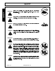
SAFETY SAFETY WARNING! Always read instructions carefully when and handling comply oil, fully solvents, with the cleansers, manufacturers and any other chemical agent. DANGER! Never run the Power Unit engine in a closed building or without adequate ventilation. The exhaust fumes can be hazardous to your health. DANGER! KEEP AWAY FROM ROTATING ELEMENTS to prevent entanglement and possible serious injury or death.
SAFETY WARNING! Never interfere with factory-set hydraulic calibrations. Any change in calibration could cause a failure of the equipment and result in injury. Always shut the Power Unit completely down, place the transmission in park, and set the parking brake before you or anyone else attempts to connect or disconnect the Loader. DANGER! Never crawl under a raised implement supported solely by the Power Unit boom.
SAFETY SAFETY 5 6 6 2 8 1 3 3 7 4 RIGHT SIDE FRAME LEFT SIDE FRAME 9 9 F-3672-1-02 © 2001 Alamo Group Inc.
SAFETY SAFETY ITEM PART NO. QTY. TYPE DESCRIPTION 1 2 3 4 5 6 7 8 9 26871 7794 38789 36932 49696 35674-6 48921 48858 00776481 1 1 2 1 2 1 1 1 1 WARNING CAUTION MODEL WARNING LOGO STRIPE DANGER DANGER MANUAL CANISTER To Prevent Instability Loader Safety Guides 104QX Avoid Injury During Installation Rhino Silver, 13.5 ft.
SAFETY NOTE: Safety decal location is listed below each decal. illegible. Replace Replacement decal if decals damaged are or available SAFETY from your dealer. 2 - - 7794 1 - - 26871 DANGER 7- - 48921 4 - - 36932 F-3672-1-02 © 2001 Alamo Group Inc.
SAFETY SAFETY 3 - - 38789 6 - - 35674-6 ® 49696 5 - - 49696 9 - - 00776481 DANGER Keep bucket and boom away from overhead electric lines. Failure to comply will result in serious injury or death.
SAFETY SAFETY FEDERAL LAWS AND REGULATIONS This section is intended to explain in broad terms the concept and effect of federal laws and regulations concerning employer and employee equipment operators. This section is not intended as a legal interpretation of the law and should not be considered as such. Employer-Employee Operator Regulations U.S. Public Law 91-596 (The Williams-Steiger Occupational and Health Act of 1970) OSHA This Act Seeks: “...
INTRODUCTION SECTION Introduction Section 2-1
INTRODUCTION INTRODUCTION INTRODUCTION This manual provides operation, maintenance, assembly and parts identification for your new loader. Your loader has been designed to give many years of satisfactory service. Successful operation and long life of the loader depends on proper maintenance and operation. Please read this manual carefully and follow all instructions. Correct assembly, operation and maintenance will save you much time and expense.
INTRODUCTION SPECIFICATIONS Specifications will vary with tractor, tire size, hydraulic system and bucket used. The specifications are given for a loader equipped with 72" HD material bucket operated with an average tractor hydraulic system of 20 GPM with engine operating at 2200 RPM and control valve relief setting of 2200 PSI. Break-away Capacity . . . . . . . . . . . . . . . . . . . . . . . . . . . . . 3770# Lift capacity at Full Height . . . . . . . . . . . . . . . . . . . . . . . . . . .
ASSEMBLY SECTION Assembly Section 3-1
ASSEMBLY ASSEMBLY INSTRUCTIONS INSTALLING BUCKET Attach bucket to the lift boom frame and bucke? cylinders INSTALLING MOUNTING BRACKETS with 1-1/4 x 5-1/2 pins (9). 3/8 x 1" shoulder bolts (15) and Install all mounting brackets on the tractor according to lock nuts (20). instructions packed with mounting kit.
ASSEMBLY DISMOUNTING AND MOUNTING LOADER mounting bracket and mid mounting brackets. This can also be accomplished by using the boom float IMPORTANT: position if the valve used to control the lift cylinders is The loader must be equipped with a so bucket to dismount the loader from the tractor. equipped. disengage NOTE: The loader should be stored in a dry place. Move front the support tractor bracket backwards tube from to front mounting bracket channel.
ASSEMBLY PREPARING STORED LOADER FOR MOUNTING MOUNTING PROCEDURE If the loader has been completely collapsed for long-term The storage, it is necessary to expand the loader first, before it dismounting mounting procedure is basically the reverse of can be mounted on the tractor. Follow the instructions below which apply to your loader, depending on what 1.
OPERATION SECTION Operation Section 4-1
OPERATION PREPARING TRACTOR Loaders with 2-lever controls, ease both levers back to lift Before operating loader, for optimum stability, additional and roll back bucket. weight should be added to rear of tractor with rear wheel weights or liquid ballast. Refer to your tractor operator's manual for weighting information. The tractor rear wheels should be moved to the tractor manufacturer's widest recommended settings to increase the stability of the tractor.
OPERATION LIFTING THE LOAD When When lifting the load, keep the bucket positioned to avoid transporting the load, keep bucket as low as possible, to avoid tipping, in case a wheel drops in a rut. spillage. DUMPING THE BUCKET Lift bucket high enough to clear side of vehicle. Move tractor in as close as possible to side of vehicle, then dump bucket. CAUTION: Do not attempt to lift loads in excess of loader capacity.
OPERATION OPERATING WITH FLOAT CONTROL During hard surface operation, keep bucket level and put lift control in float position to permit bucket to float on working surface. If hydraulic down pressure is exerted on bucket, it will wear faster than normal. Sidecutting is a good technique for cutting down a big pile. Float will also prevent mixing of surface material with stockpile material.
OPERATION PEELING AND SCRAPING Use a slight bucket angle, travel forward and hold lift control forward to start the cut. Make a short 5 to 8 foot Backgrade occasionally with a loaded bucket to keep working surface free of ruts and holes. Also, hold lift control forward so full wieght of bucket is scraping ground. angle cut and break out cleanly. BACKFILLING With bucket level, start a cut at notch approximately 2 inches deep. Hold depth by feathering bucket control to adjust cutting lip up or down.
OPERATION Leave dirt in bucket. Dumping on each pass wastes time. Pile dirt on high side for easier backfilling on a slope. HANDLING LARGE HEAVY OBJECTS DANGER 1. Using front end loaders for handling large heavy objects such as large round or rectangular bales, logs and oil drums is not recommended. Operate at right angles to ditch. Take as big a bite as 2. tractor can handle without lugging down.
OPERATION GRASPING ROUND BALES OPERATING GRAPPLE FORK Operation of your tractor and loader with grapple fork Approach bale with grapple fork open and bucket level. option Use loader float position if bale is on ground.
OPERATION Position bucket just below level of tractor hood for maximum stability and visibility whether bucket is loaded or empty. LOADING INTO TUB GRINDER Lift bucket high enough to clear tub grinder sides. Move tractor toward tub grinder to position load near center. Extend bucket cylinders to position bucket in dump attitude. Use extreme care when operating loader on a slope. Carry load as low as possible.
OPERATION Use loader and grapple fork to gently position bale on An alternative method is to use your loader and grapple stack, then release bale while removing bucket and fork. fork to knock material down from top of pile so it can be loaded from ground. Slowly back tractor away from stack. Exercise caution when undercutting a high pile. Avalanching material can be dangerous.
MAINTENANCE SECTION Maintenance Section 5-1
MAINTENANCE MAINTENANCE F-3672-1-02 Maintenance Section 5-2
MAINTENANCE MAINTENANCE F-3672-1-02 Maintenance Section 5-3
MAINTENANCE MAINTENANCE F-3672-1-02 Maintenance Section 5-4
MAINTENANCE MAINTENANCE remove F-3672-1-02 © 2001 Alamo Group Inc.
MAINTENANCE Regular maintenance of your loader and hydraulic system HYDRAULIC PRESSURE CHECK will insure maximum loader efficiency and long life. Following procedure outlines hydraulic pressure check. WARNING: beneath a properly NEVER raised perform loader supported to maintenance unless loader prevent is 1. accidental Obtain a pressure gauge that measures 3000PSI in 50 PSI increments. lowering. 2.
MAINTENANCE MAINTENANCE set screw. F-3672-1-02 © 2001 Alamo Group Inc.
MAINTENANCE GENERAL TORQUE SPECIFICATIONS USE THE FOLLOWING TORQUES WHEN SPECIAL TORQUES ARE NOT GIVEN AMERICAN STANDARD CAP SCREWS SAE 5 8 Metric Class 8.8 10.9 TORQUE TORQUE Cap Screw TORQUE TORQUE Grade Cap Screw MAINTENANCE Size METRIC CAP SCREWS FT-LBS Nm FT-LBS Nm Size FT-LBS Nm FT-LBS Nm Inches MIN MAX MIN MAX MIN MAX MIN MAX Millimeters MIN MAX MIN MAX MIN MAX MIN 1/4-20 6.25 7.25 8.5 10 8.25 9.
RHINO LIMITED WARRANTY 1. LIMITED WARRANTIES 1.01. Rhino warrants for one year from the purchase date to the original non-commercial, governmental, or municipal purchaser (Purchaser) and warrants for six months to the original commercial or industrial purchaser (Purchaser) that the goods purchased are free from defects in material or workmanship. 1.02. Manufacturer will replace for the Purchaser any part or parts found, upon examination at one of its factories, to be 1.03.
TO THE OWNER/OPERATOR/DEALER In addition to the standard Limited Warranty shown on the facing page, Rhino also provides: 1. A TWO-YEAR (24 months) LIMITED WARRANTY* on non-perishable structural items such as: Loader Boom, Side Frames, Mount Brackets, Backhoe Boom, Dipper, Main Frame, Stabilizer Legs, Swing Bracket, Subframe and Related Mounting Brackets provided they have not been subjected to abuse or misuse and have been properly maintained as noted.
® TO THE OWNER/OPERATOR/DEALER To keep your implement running efficiently and safely, read your manual thoroughly and follow these directions and the Safety Messages in this Manual. The Table of Contents clearly identifies each section where you can easily find the information you need. The OCCUPATIONAL SAFETY AND HEALTH ACT (1928.51 Subpart C) makes these minimum safety requirements of tractor operators: REQUIRED OF THE OWNER: 1.
® 104QX-SOM-1-02 Printed U.S.A.