
User Manual

GB
25469186_c
Snow Line 560 II, 620 II, 620E II
Use the skid plates to adjust the distance of the
clearingplatefromthesurface.Donotoperate
themachineongravelsurfaces.
Neverliftorcarrythemachinewhiletheengineis
running.
Donoteat,drinkorsmokewhilellingwithpetrol
or engine oil.
Donotinhalepetrolfumes.
Take precautions to ensure that discharged snow
doesnotcauseinjurytopersonsoranimalsor
damagetobuildings,vehiclesorotherobjects.
Makesurethattrafcisnotimpairedandthatdriv-
ers are not endangered.
Keep hands out of the snow discharge chute while
themachineisrunning.
Keephandsandfeetawayfromtheaugerandim-
pellerwhilethemachineisrunning.
Donotclearsnowfromroofs.
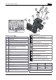
Assembly
Caution!
Donotoperatethemachineuntilithasbeenfully
assembled.
Required tools
2 Open-end or ring spanners, size 10
Open-end or ring spanner, size 13
Hexkey,5mm
Combinationorneedlenosepliers
Screwdriver
Spray oil
Tyrepumpwithpressuregauge(autotyrevalve)
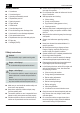
Assembly sequence
Attaching and adjusting control cables
Thesameprocedureappliesforthewheeldrive
and auger control cables.
1. Guide the control cable upward:
Guide the auger control cable through the
opening on the drive speed selection plate
(
3-1).
Guide the wheel drive control cable upward
under the drive speed selection plate (
3-2).
2. Loosenthescrewwiththehookfromtheadjust-
mentnut(
4-1).Thelocknutremainsonthe
screw.
3. Raise the clutch lever (
5).
4. Mount the hook into the hole on the clutch lever
fromtheguidehandleside(
6).
5. Screwtheadjustmentnuttotheattachedscrew
until there is no slack in the cable (lightly tightened)
(
7-1). Hold the cable while tightening so that it
does not twist.
6. Tighten the lock nut (
7-2).
x The control cables are installed.
Attaching the drive speed selection lever
1. Guidethepre-assembleddrivespeedselection
lever through the drive speed selection plate
(
8-1).
2. Removethemountingscrewfromtheconnection
bolt and attach the drive speed selection lever
(
9).
3. Secure the drive speed selection lever with the
horizontalmountingscrew(
10-1). Do not tighten
the screw yet.
4. Adjusttheleverpositionwiththeadjustmentscrew
sothatitengagesintotheslotfortherstspeed
setting (1) (
8-2).
5. Locktheadjustmentscrew(
10-2).
6. Tightenthemountingscrewwiththeself-locking
nut (
10-1).
x The drive speed selection lever is attached.
Attaching the snow discharge chute
1. Lightly lubricate the surface of the snow discharge
chute that slides against the snow blower with
spray oil (
11).
2. Mount the discharge chute (
11).
3. Insertmountingscrewsintothelower,largerguide
plateandattachthesmallerguideplate(
12-1).