
User manual

Operation
akYtec GmbH · Vahrenwalder Str. 269 A · 30179 Hannover · Germany · Tel.: +49 (0) 511 16 59 672-0 · www.akytec.de
8
6 Operation
The operating mode is automatically enabled as soon as the device is supplied with power.
The device supports master and slave modes. The mode can be set in the parameter dEv.r (see Table D3).
The factory setting is 0 (slave).
6.1 Slave mode
In the slave mode the SMI2 receives the data from the master and processes it in accordance with the oper-
ating parameters. The results are shown on the display.
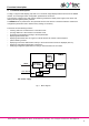
6.2 Master mode
To enable the master mode, the parameter dEv.r must be set to 1. To do this the “Factory settings” mode
must be temporarily activated (see 5.5).
In the master mode the SMI2 sends requests to the slave device in the set cycle (parameter SLA.P). The
following parameters must be configured:
– SLA.A - Address of the slave in the network
– SLA.r - Register number for the request
– SLA.P - Query cycle with increment of 100 ms, standard value – 10 (= 1 s)
– SLA.F - Modbus reading function (0x0003 or 0x0004)
The transmitted values are displayed in the same way in both modes in accordance with the set operating
parameters.
►
NOTICE
The master mode supports only the protocol Modbus RTU/ASCII
The device cannot be programmed in the master mode. To do this the “Factory
settings” mode must be temporarily activated (see 5.5).
6.3 Operating parameters
The complete parameter list is provided in the Table D3.
The data type (Int, Word, Float, String, Image) for the data transmission is set in the parameter dAtA.
For data types Int and Word the transmitted values are displayed with the set decimal point position (pa-
rameter dP).
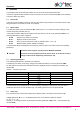
Table 6.1 Decimal point position
Parameter dP
Display
Factor
0
----
1
1
----.
1
2
---.-
10
-1
3
--.--
10
-2
4
- .---
10
-3
The transmitted value is displayed with or without flashing, depending on whether the value lies within or
outside the alarm limits, and the set alarm logic. The flashing interval is set in the parameter PF.
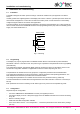
6.4 Alarm logic
Any exceedance of the alarm limits is displayed by flashing LEDs in accordance with the alarm logic.
∩-Logic (parameter AL.t = 1) − the display flashes if the current value lies within the interval
(Т – Δ) < t < (T + Δ),
whereby T − is the setpoint of the monitored process value (parameter C.SP) and Δ − is the hysteresis (pa-
rameter HYST).