
User manual


Installation and commissioning
akYtec GmbH · Vahrenwalder Str. 269 A · 30179 Hannover · Germany · Tel.: +49 (0) 511 16 59 672-0 · www.akytec.de
6
5 Installation and commissioning
5.1 Installation
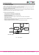
The SMI2 is designed for switch panel mounting in a borehole of Ø22.5 mm (see Appendix A for dimen-
sions).
Carefully position the supplied gasket on the display rear surface. Insert the cylindrical part of the device into
the borehole and tighten the nut from the rear side of the switch panel. Connect the device to the auxiliary
voltage and signal cables in accordance with Appendix B.
The factory settings can be changed before assembly if necessary (see Appendix D.3). For this purpose the
device must be connected to the RS485 interface of the programming device (PC) and to the auxiliary power
supply. For further details see 5.3.
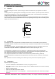
Fig. 2 Mounting
5.2 Programming
The display may only be programmed in the RS485 network with the communications protocol Modbus
RTU/ASCII or akYtec in the slave mode. The protocol type is specified in the parameter Protocol type (t.Pro)
(see Table D3).
The configuration software „Konfigurator SMI2“ allows to configure the device via the akYtec protocol. The
CD with the configuration software is supplied with the device. Further steps are given in 5.3.
The parameters are divided into two main groups: the configuration parameters and transmitted data.
The configuration parameters are device information, network parameters and operating parameters. The
latter determine how the device processes the received information.
The configuration parameters are constants and are saved in the permanent memory (Table D3).
The transmitted data are variable data exchanged between the master and slave. These are not saved (Ta-
ble D4).
Each parameter has a name consisting of Latin letters (up to four), which can be separated by points.
5.3 Configuration
Required steps for configuration:
– Connect a USB/RS485 or RS232/RS485 converter (not supplied) to the PC
– Connect the display to the 24 V DC power supply and to the RS485 terminals of the converter according
to Fig. B1
– Switch on auxiliary voltage
– Install and start SMI2 configuration software
– In the menu select “Device -> Port configuration…“ and set the parameters to the device factory settings
(see 5.5)
Switch panel
Gasket
Nut
Enclosure