
User manual
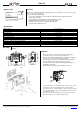

Wiring diagrams
Fig. 4 Connection from the right
Fig. 5 Connection from the left
Fig. 6 Two side connection
(terminals 1, 4 or 2, 3)
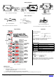
Wire connection
Fig. 7 Wire preparation
Fit the stranded wire with a wire end ferrules
Fig. 8 Connecting the wire to the
terminal
Fig. 9 Disconnecting the wire
Press the actuation lever and the contact is opened
Programming
Operation
Fig. 10 Flowchart
Conversion functions
linear function
LodiHidi
I
LodiT ..
16
4
.
square root function
LodiHidi
I
LodiT ..
16
4
.
where
T – displayed value corresponding to input signal I, mА
di.Lo – Lower limit, corresponds to 4 mA
di.Hi – Upper limit, corresponds to 20 mA
Display messages
Display
Cause
Input current lower than 3.8 mA
Input current higher than 22.5 mA
« »
Upper menu line has been reached
« »
Lower menu line has been reached
not lit
No input signal
Polarity reversal
With particular setting parameters the device cannot actually
display the necessary 5 figures due to the restriction to four
segments.
Example
The parameters are configured as follows:
di.Lo: -999 4 mA
di.Hi: 9999 20 mA
With an input measured current of 20.8 mA the correct display
should be “10548”. Due to the restriction to four segments, the
first character is removed and the display is “0548”.
Maintenance
The maintenance includes:
– cleaning the housing and the terminals from dust, dirt and debris
– checking the fastening of the device
– checking the wiring (connecting leads, fastenings, mechanical damage)
The device should be cleaned with a damp cloth only. No abrasives or solvent-containing cleaners may be used.
ITP11-W_0129_EN
© All rights reserved. Subject to technical changes and misprints.
akYtec GmbH · Vahrenwalder Str. 269 A · 30179 Hannover · Germany
Tel.: +49 (0) 511 16 59 672-0 · www.akytec.de