
Instructions

Program examples
akYtec GmbH · Vahrenwalder Str. 269 A · 30179 Hannover · Germany · Tel.: +49 (0) 511 16 59 672-0 · www.akytec.de
93
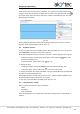
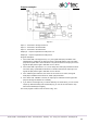
If the button SB1 is pressed, the RS trigger D1 becomes True as long as there is no reset
signal at the input R. Subsequent signal path depends on the state of the switch SA1
“MODE”:
If SA1 is open (Manual mode), the logical AND (D7) and the logical OR (D8) are ena-
bled and the motor M1 (output Q1) is switched on.
If SA1 is closed (Automatic mode), the logical AND (D7) is disabled and the start sig-
nal can only activate the pulse generator BLINK (D5) to start the operating cycle (15 s
on / 10 s off) and the on-delay timer TON (D4) to stop it (in 5 min).
2. Input I3 (SB2 “STOP”)
If the button SB2 is pressed or the switch F1 is activated, the RS trigger D1 is reset
over the input R and the output Q1 is disabled.
3. Input I1 (SA1 “MODE”)
If the switch SA1 is open (Manual mode), the logical AND D3 is disabled and D7 is
enabled, the timer D4 and the pulse generator D5 are disabled and the motor M1 can
be only started with SB1 and stopped with SB2.
If the switch SA1 is closed (Automatic mode), the logical AND D3 is enabled and D7
is disabled, thus the motor M1 can be only started by the pulse generator D5 (15 s on
/ 10 s off cycle) and stopped by the timer D4 in 5 minutes.
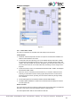
4. Input I6 (overload switch F1)
When the motor is overloaded, the F1 contact is closed, the RS trigger D1 is reset
and the motor is stopped.
Concurrently the signal lamp HL1 is switched on over the logical OR (D12) and the
acoustic signal HA1 is activated over the RS trigger D9. The pulse generator D10
provides an intermittent acoustic signal with the cycle 3 s on / 3 s off.
5. Input I7 (SB3 “RESET”)
The button RESET is used to reset the acoustic signal HA1. If the button SB3 is
pressed, the RS trigger D9 is reset and the pulse generator D10 for the acoustic sig-
nal HA1 is stopped.
6. Input I8 (SB4 “TEST”)
The button TEST is used to test the acoustic signal HA1 and the signal lamp HL1. If
the button SB4 is pressed, the logical ORs D11 and D12 are enabled, the outputs Q2
and Q3 activated, the acoustic signal and the lamp are switched on.
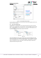
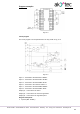
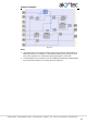
The circuit program is shown in Fig. 10.6.