
Instructions

Program examples
akYtec GmbH · Vahrenwalder Str. 269 A · 30179 Hannover · Germany · Tel.: +49 (0) 511 16 59 672-0 · www.akytec.de
92
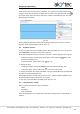
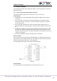
Fig. 10.4
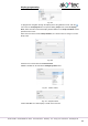
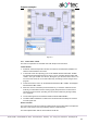
Circuit program
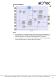
The circuit program can be implemented in the way shown in Fig. 10.5.
Fig. 10.5
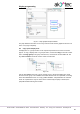
Input I1 – connected to the switch SA1 “MODE”
Input I2 – connected to the button SB1 “START”
Input I3 – connected to the button SB2 “STOP”
Input I6 – connected to the overload switch F1
Input I7 – connected to the button SB3 “RESET”
Input I8 – connected to the button SB4 “TEST”
Output Q1 – connected to the motor
Output Q2 – connected to the acoustic signal HA1
Output Q3 – connected to the signal lamp HL1
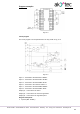
Program description:
1. Input I2 (SB1 “START”)