
Instructions


Program examples
akYtec GmbH · Vahrenwalder Str. 269 A · 30179 Hannover · Germany · Tel.: +49 (0) 511 16 59 672-0 · www.akytec.de
90
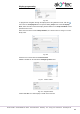
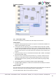
Fig. 10.2
Input I1 – connected to the light sensor F1
Input I2 – connected to the button SB1
Input I3 – connected to the switch SA1
Output Q1 – output to implement the task points 1-4
Output Q2 – output to implement the task point 5
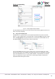
Program description:
1. If the button SB1 is shortly pressed (< 2 s), the logical AND (D2) is enabled. If the
ambient light is insufficient, the first input of D2 is also True and the timer TP “Pulse”
(D3) forms a pulse with 1 minute duration. This pulse activates the output Q1 over the
logical OR (D6) and the light is switched on for 1 minute.
2. If the button SB1 is pressed for > 2 s, the on-delay timer TON (D4) activates the timer
TP “Pulse” (D5), a pulse with the duration of 3 minutes activates the output Q1 over
logical OR (D6) and the light is switched on for 3 minutes.
3. If the ambient light is sufficient, the contact of the sensor F1 is closed, the logical
AND (D2) is disabled and the timer TP “Pulse” (D3) is blocked.
4. If the switch SA1 “CONST” is closed, the output Q1 is activated over the logical OR
(D6) and the light is switched on constantly.
5. If you want to use the light only on certain weekdays at certain times, you can use the
output Q2. With the weekly timer CLOCKW (D7) you can set the start and the stop
time and the weekdays for lighting.
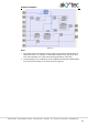
The circuit program created in ALP is shown in Fig. 10.3.