
Instructions

Device configuration
akYtec GmbH · Vahrenwalder Str. 269 A · 30179 Hannover · Germany · Tel.: +49 (0) 511 16 59 672-0 · www.akytec.de
33
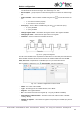
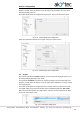
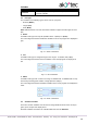
To create several variables with the same settings, select a variable and click the icon
Duplicate.
Fig. 4.20 Variable duplication
Name – the name of the duplicated variable
Start number – the initial number added to the name of the duplicated variable
Quantity – the quantity of the duplicated variables
Address step – the address increment
Click OK to add the duplicated variables to the list of variables. The variables will be
stored in adjacent register cells with consecutive addresses.
To remove the variable from the list, use the icon Delete.
4.4 Extension modules
Up to two I/O extension modules of type PRM can be connected to PR200. For further in-
formation about extension modules refer to the PRM user guide.
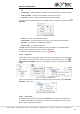
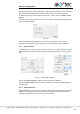
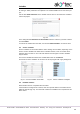
To use module I/O points in the circuit program, add the module to the group Extension
modules using its context menu (Fig. 4.21).
Fig. 4.21
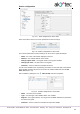
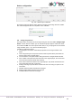
The additional I/O points of the added modules can be configured in branches Inputs and
Outputs respectively (sect. 4.5, 4.6). They are displayed in the tree as Ix(y) and Qx(y)
respectively, where x is the ordinal number of the I/O points on the module and y is the
ordinal number of the module counting from the basic device.
Fig. 4.22
Before uploading the project to the basic device, all modules must be connected via the
internal bus to PR200 and powered on. The module firmware is synchronized with the
current version of ALP when project uploading.
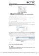
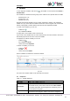
4.5 Inputs
The content of the branch Inputs depends on the resources of the target device. It can be
analog and/or digital inputs (Fig. 4.23, 4.24).